
Cutting device for high-strength glass

A cutting device and high-strength technology, applied in glass cutting devices, glass manufacturing equipment, manufacturing tools, etc., can solve the problems of wasting water resources, glass fixing is not firm enough, etc., and achieve the effects of saving energy, improving precision, and ensuring stability

Inactive Publication Date: 2018-02-16
防城港市亿尚鑫艺术玻璃有限公司
View PDF5 Cites 9 Cited by
  • Summary
  • Abstract
  • Description
  • Claims
  • Application Information

AI Technical Summary

Problems solved by technology

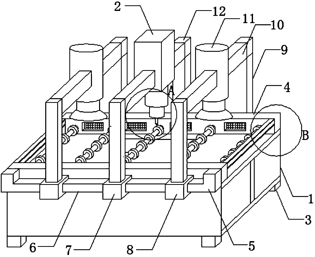
[0004] The purpose of the present invention is to provide a cutting device for high-strength glass in order to solve the problems of insufficient glass fixation and waste of water resources in dust removal

Method used


Image

  • Cutting device for high-strength glass
  • Cutting device for high-strength glass
  • Cutting device for high-strength glass

Examples


Embodiment 1

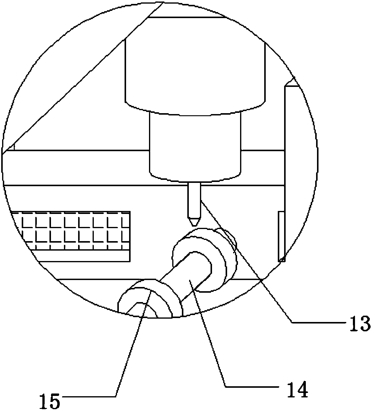
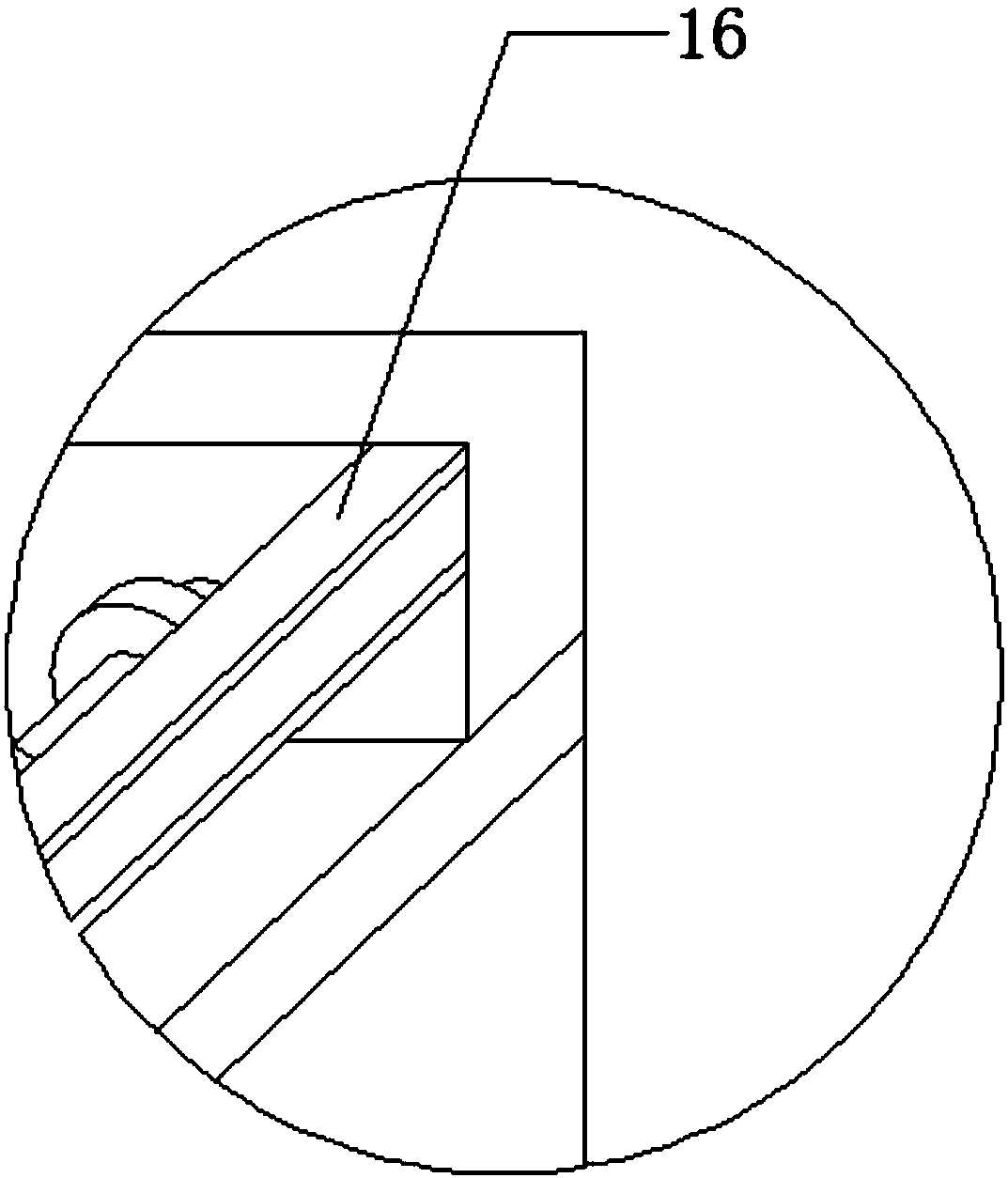
[0024] see Figure 1-5 As shown, a high-strength glass cutting device includes a cabinet 1 and a cutting cabinet 2. The bottom of the cabinet 1 is welded with several legs 3, and the legs 3 are evenly distributed on the four bottom corners of the cabinet 1. Both sides of the top of the cabinet 1 are Weld the baffle plate 4, weld the fixing seat 5 at both ends of the side wall of the baffle plate 4, weld the slide bar 6 between the two fixing seats 5, the middle part of the slide bar 6 engages the first slider 7, and both sides of the first slider 7 are Engage the second slider 8, and the first slider 7 and the two second sliders 8 can slide to adjust the position on the slider 6, and the top of the second slider 8 is welded to the support rod 9,, the support rod 9 The beam 10 is welded on the top, and the middle part of the beam 10 is engaged with the hydraulic pump 11, and the hydraulic pump 11 can drive the hydraulic rod 20 to move up and down. A number of rotating shafts 1...

Embodiment 2

[0026] In addition, please continue to Figure 2-5 As shown, the difference between it and Embodiment 1 is that both the first slider 7 and the second slider 8 are engaged on the slider 6 through the slot 23, and the first slider 7 and the second slider 8 are both connected to the The slide bar 6 is movably connected, so that the first slide block 7 and the second slide block 8 can slide to adjust the position, which is convenient for the cutting machine case 2 to cut different positions, and can absorb and fix the glass by the suction cup 21 during the cutting process, ensuring The stability of the glass, the cutting box 2 is set in the middle of the bracket 12, and the cutting box 2 is set directly above the cabinet 1, so that the cutting box 2 can just cut the glass placed on the top of the cabinet 1, and the fan 18 is set through the fixed frame 19 Inside the baffle plate 4, the fan 18 is electrically connected to the external power supply through wires, so that the fan 18...


PUM


Abstract

The invention discloses a cutting device for high-strength glass. The cutting device comprises a machine cabinet, a cutting machine case, support legs, baffles, fixed seats, a slide rod, a first slideblock, second slide blocks, support rods, crossbeams, hydraulic pumps, a bracket, a cutting pen, a rotating shaft, rollers, clam plates, air holes, fans, a fixed frame, hydraulic rods, suction discs,an air escape valve and clamp slots. The cutting device has the beneficial effects that the two suction discs are arranged above the machine cabinet, can move left and right, can be adjusted up and down and can adsorbed and fixed to two sides of a to-be-cut position of a glass board, so that the stability of glass in the cutting process is guaranteed, and the cutting precision can be effectivelyimproved; a plurality of fans are uniformly arrayed on the side walls of the baffles, so that broken glass produced in the cutting process can be extracted and collected by virtue of rotating fans, the situation that the broken glass is scattered into air is prevented, and the problem that water resource is wasted by virtue of a water cutting method is solved; and the cutting device is strong in flexibility and high in cutting precision.

Description

technical field [0001] The invention relates to a cutting device, in particular to a cutting device for high-strength glass, and belongs to the technical field of glass processing equipment application. Background technique [0002] Glass is formed by melting silica and other chemicals together. A silicate-based non-metallic material that forms a continuous network structure during melting, and gradually increases in viscosity and hardens during cooling to cause it to crystallize. High-strength glass is to add some elements to ordinary glass to make it reach a certain strength. The cutting device of high-strength glass is a kind of mechanical equipment specially used for cutting and processing glass. [0003] But existing cutting device still has certain defective when using, although existing cutting device can cut glass, in the process of cutting, because the glass is fixed not firm and stable enough, the vibration that produces during cutting can make glass occur. Offse...

Claims


Application Information

Patent Timeline
IPC IPC(8): C03B33/023
CPCC03B33/023
Inventor 陈丽
Owner 防城港市亿尚鑫艺术玻璃有限公司
Learn More