Fluid end structure of reciprocating pump

A technology of reciprocating pump and hydraulic end, applied in the field of reciprocating pump, can solve the problems of short service life of valve group, waste of manpower and material resources, inconvenient disassembly and assembly, etc., and achieve the effect of reducing friction, reducing heat generation and improving service life.

Inactive Publication Date: 2018-02-16
NINGBO QIANHU PETROLEUM EQUIP
View PDF9 Cites 5 Cited by
  • Summary
  • Abstract
  • Description
  • Claims
  • Application Information

AI Technical Summary

Problems solved by technology

[0004] The liquid end structure of the above-mentioned high-pressure reciprocating pump is affected by the conveying medium, pressure, etc., resulting in a variety of liquid end structures, which cannot meet the various need

Method used


Image

  • Fluid end structure of reciprocating pump
  • Fluid end structure of reciprocating pump

Examples


Example Embodiment

[0028] The following are specific embodiments of the present invention in conjunction with the accompanying drawings to further describe the technical solutions of the present invention, but the present invention is not limited to these embodiments.
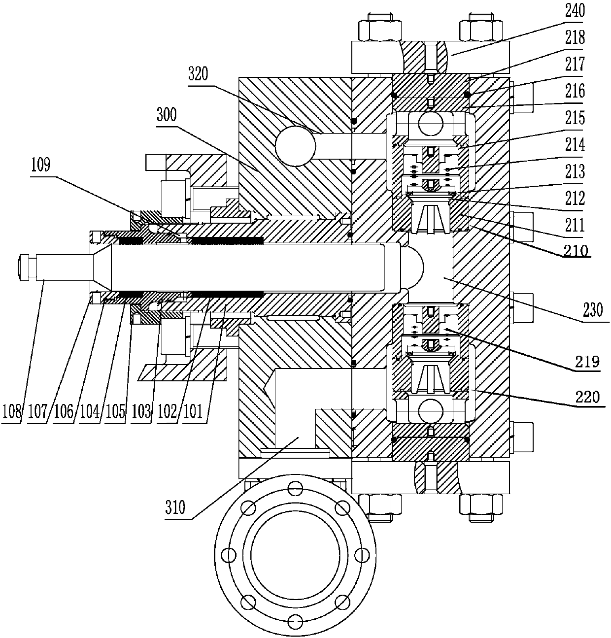
[0029] Please refer to figure 1 , The hydraulic end structure of a reciprocating pump of the present invention includes a supporting main pump body 300, a valve cavity 200 and a plunger 108.

[0030] The supporting main pump body 300 is closely connected to the valve cavity 200, and the plunger 108 penetrates the supporting main pump body 300 and extends into the valve cavity 200.

[0031] The valve cavity 200 is provided with a valve block module, the valve block module is provided with a liquid inlet valve group 220, a liquid discharge valve group 210 and a first cavity 230; the first cavity 230 is located in the liquid inlet valve Between the group 220 and the drain valve group 210, the first cavity 230 is T-shaped.

[0032] A flange ...


PUM


Abstract

The invention discloses a fluid end structure of a reciprocating pump. The fluid end structure of the reciprocating pump comprises a supporting main pump body, a valve cavity body fixedly connected with the supporting main pump body and a plunger piston. The plunger piston penetrates the supporting main pump body and stretches into a first cavity of valve set modules. The outer wall of the plungerpiston is sleeved with a main seal box assembly and an auxiliary seal box assembly. The main seal box assembly is arranged between the outer wall of the plunger piston and the supporting main pump body. The auxiliary seal box assembly is arranged between the outer wall of the plunger piston and the main seal box assembly. Lubricating grease is fed into the main seal box assembly and the auxiliaryseal box assembly of the fluid end structure, friction between the plunger piston and packing can be reduced, heat can be reduced, and the service life of the plunger piston and the service life of the packing can be prolonged. The valve set modules can be freely combined in different machine types to adapt to various media, high-pressure liquid conveying can be achieved, a valve core adopts nonmetal and metal combined type seal, nonmetal valve face contact is carried out before metal valve face contact is carried out, and the service life of a valve set is prolonged.

Description

technical field [0001] The invention relates to the technical field of reciprocating pumps, in particular to a fluid end structure of a reciprocating pump. Background technique [0002] A reciprocating pump is a positive displacement pump that relies on the reciprocating movement of a piston, plunger or diaphragm in a pump cylinder to alternately increase and decrease the working volume in the cylinder to deliver or pressurize liquid. [0003] The existing notification number is CN204941896U, a hydraulic end structure of a high-pressure reciprocating pump, including a pump head, a valve group, and a stuffing box. The valve group is arranged inside the pump head, and the pump head is connected to a bracket. It is fixed on the pump head through a bracket, and the stuffing box, bracket and pump are connected by hexagon socket head screws, and a first O-ring is provided at the joint between the pump head and the stuffing box, and the stuffing box includes a stuffing box , plung...

Claims


Application Information

Patent Timeline
IPC IPC(8): F04B53/10F04B53/18F04B53/00F04B53/02F04B53/14
CPCF04B53/10F04B53/00F04B53/02F04B53/14F04B53/18
Inventor 郑上军贾品元左周高贵斌汪勇白云龙王治宁王海鹏赵兰坤樊亚宁
Owner NINGBO QIANHU PETROLEUM EQUIP
Why Eureka
Try Eureka