Speed reducer ventilation device

A technology of ventilation device and reducer, applied in transmission parts, belts/chains/gears, mechanical equipment, etc., can solve problems such as oil leakage, damage to parts, inability to set the air pressure value, etc., to avoid falling off, ensure accuracy, Avoid offset effects

Inactive Publication Date: 2018-02-16
吕丽娅
View PDF3 Cites 1 Cited by
  • Summary
  • Abstract
  • Description
  • Claims
  • Application Information

AI Technical Summary

Problems solved by technology

[0007] Based on the technical problems existing in the background technology, the present invention proposes a reducer ventilation device, which has the characteristics of adjusting the air pressure value when the reducer is ventilated, and solves the problem that the existing reducer ventilation device cannot set the air pressure value and cannot adjust the air pressure value of the reducer. The air pressure value, resulting in damage to parts or oil leakage

Method used


Image

  • Speed reducer ventilation device
  • Speed reducer ventilation device
  • Speed reducer ventilation device

Examples


Embodiment Construction

[0018] The following will clearly and completely describe the technical solutions in the embodiments of the present invention with reference to the accompanying drawings in the embodiments of the present invention. Obviously, the described embodiments are only some, not all, embodiments of the present invention. Based on the embodiments of the present invention, all other embodiments obtained by persons of ordinary skill in the art without making creative efforts belong to the protection scope of the present invention.

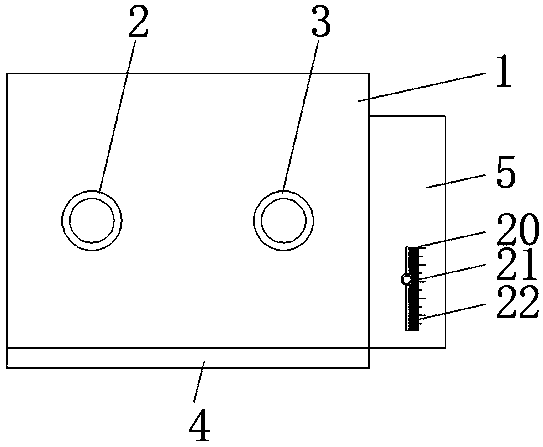
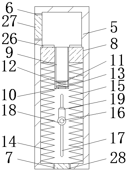
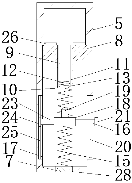
[0019] see Figure 1-3 , the present invention provides a technical solution: a reducer ventilation device, including a reducer 1, the left side of the front of the reducer 1 is rotatably connected to a high-speed shaft 2, and the front of the reducer 1 is rotatably connected to the right side of the high-speed shaft 2 There is a low-speed shaft 3, the bottom of the reducer 1 is welded with a base 4, the bottom on the right side of the reducer 1 is connected w...


PUM


Abstract

The invention discloses a reducer ventilation device, comprising a reducer, a high-speed shaft is rotatably connected to the left side of the front of the reducer, and a low-speed shaft is rotatably connected to the front of the reducer and located on the right side of the high-speed shaft. The bottom of the reducer is welded with a base, the bottom of the right side of the reducer is connected with a ventilation device through bolts, the top of the left side of the ventilation device and the position corresponding to the reducer are provided with a first air hole, and the surface of the inner wall of the ventilation device is provided with a first air hole. A sealing gasket is slidably connected to the bottom of the first air hole, and a ventilation pipe is communicated with the bottom of the sealing gasket. The reducer ventilation device solves the problem of the current situation through the cooperation of the ventilation device, the gasket, the ventilation pipe, the ventilation hole, the fixed rod, the first spring, the second spring, the third spring, the first chute, the ejector rod and the air pressure scale line. Some reducer ventilation devices cannot set the air pressure value, and cannot adjust the air pressure value when the reducer is ventilated, resulting in damage to parts or oil leakage.

Description

technical field [0001] The invention relates to the technical field of mechanical equipment, in particular to a ventilating device for a reducer. Background technique [0002] Various reduction mechanisms are widely used in the mechanical field. In order to avoid affecting the normal operation of the reducer due to excessive pressure inside the reducer, there is usually a ventilation device on the reducer, whose function is to communicate the inside of the reducer with the outside atmosphere when the gas pressure in the reducer body is too high , so that the internal pressure of the reducer is reduced, and the internal pressure of the reducer is too high to avoid damage to the internal parts of the reducer or oil leakage. The existing reducer ventilation device is always in a state of being connected to the atmosphere during use, so that impurities can easily enter the reducer body, thereby causing damage to the reducer, especially in some places where the environment is re...

Claims


Application Information

Patent Timeline
Patent Type & Authority Applications(China)
IPC IPC(8): F16H57/027F16H57/029
CPCF16H57/027F16H57/029
Inventor 吕丽娅
Owner 吕丽娅
Why Eureka
Try Eureka