Infrared spot thermometer

A spot pyrometer, infrared technology

Pending Publication Date: 2018-02-16
SHENGZHOU ELECTRIC POWER +3
View PDF0 Cites 2 Cited by
  • Summary
  • Abstract
  • Description
  • Claims
  • Application Information

AI Technical Summary

Problems solved by technology

[0005] The technical problem to be solved by the present invention is to provide an infrared spot the...

Method used


Image

  • Infrared spot thermometer

Examples


Embodiment Construction

[0014] It should be noted that, in the case of no conflict, the embodiments in the present application and the features in the embodiments can be combined with each other. The present invention will be described in detail below with reference to the accompanying drawings and examples.

[0015] The following will clearly and completely describe the technical solutions in the embodiments of the present invention with reference to the accompanying drawings in the embodiments of the present invention. Obviously, the described embodiments are only some, not all, embodiments of the present invention. The following description of at least one exemplary embodiment is merely illustrative in nature and in no way taken as limiting the invention, its application or uses. Based on the embodiments of the present invention, all other embodiments obtained by persons of ordinary skill in the art without creative efforts fall within the protection scope of the present invention.

[0016] Such ...


PUM

PropertyMeasurementUnit
Center wavelengthaaaaaaaaaa

Abstract

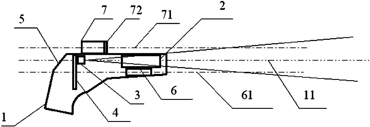
The invention discloses an infrared spot thermometer, which comprises an instrument casing, a thermal infrared lens, a thermal infrared detector, a data acquisition and display circuit, and a green laser device arranged in the instrument casing. The thermal infrared lens and the green laser device are arranged It is arranged parallel to the front side of the inner cavity of the instrument shell up and down so that the optical axis of the green laser is parallel to the optical axis of the spot temperature meter. The thermal radiation in the target position area converges on the thermal infrared detector, the data acquisition and display circuit collects the signal induced by the thermal infrared detector and displays it on the LCD screen, and the upper side of the instrument shell is equipped with a filter Sight, the filter sight is a cylindrical hollow body, a narrow band filter is installed at the front end of the cavity, the optical axis of the filter sight is parallel to the optical axis of the spot thermometer. The invention makes the target positioning of the infrared spot thermometer more accurate.

Description

technical field [0001] The invention relates to an optical instrument, in particular to an infrared spot thermometer. Background technique [0002] The traditional handheld laser positioning infrared spot thermometer emits red or green laser beams to irradiate the surface of the object, forming visible light spots on the surface of the object, so as to realize the positioning of the temperature measurement area. This kind of point thermometer is cheap and has the premise of being widely used in grassroots teams. [0003] When this kind of infrared spot thermometer targets an indoor target without direct sunlight, because the optical contrast between the laser spot and the background of the surrounding objects is high, it is easy to find the location of the laser spot. However, when measuring outdoors, if the sun shines on the target, the strong reflection of the target object will drown the red or green laser spot signal, making it difficult to identify the laser spot with ...

Claims


Application Information

Patent Timeline
IPC IPC(8): G01J5/08
CPCG01J5/0859
Inventor 童啸霄殷超倪利胡锡林凌超竺菊菊刘丹科郭勤慧孙桂付周梦兰
Owner SHENGZHOU ELECTRIC POWER
Why Eureka
Try Eureka