A clamp, a clamp pair and a stretching device

A fixture and splint technology, used in the field of tensile testing, can solve the problems of inability to accurately measure the tensile strength, inability to stably fix the sample, uneven force on the sample, and achieve uniform force, improve reliability and stability. strong effect

Active Publication Date: 2018-02-16
CHINA ELECTRONICS PROD RELIABILITY & ENVIRONMENTAL TESTING RES INST THE FIFTH ELECTRONICS RES INST OF MIITCEPREI LAB
View PDF3 Cites 5 Cited by
  • Summary
  • Abstract
  • Description
  • Claims
  • Application Information

AI Technical Summary

Problems solved by technology

[0004] Based on this, the present invention is to overcome the defects that the clamps in the prior art cannot stably fix the sample and when the tensile test is performed,

Method used


Image

  • A clamp, a clamp pair and a stretching device
  • A clamp, a clamp pair and a stretching device
  • A clamp, a clamp pair and a stretching device

Examples


Example Embodiment

[0028] In order to make the objectives, technical solutions, and advantages of the present invention clearer, the following further describes the present invention in detail with reference to the accompanying drawings and specific embodiments. It should be understood that the specific embodiments described herein are only used to explain the present invention, and do not limit the protection scope of the present invention.
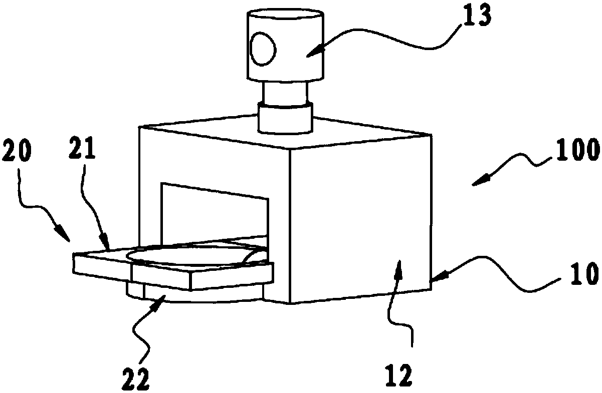
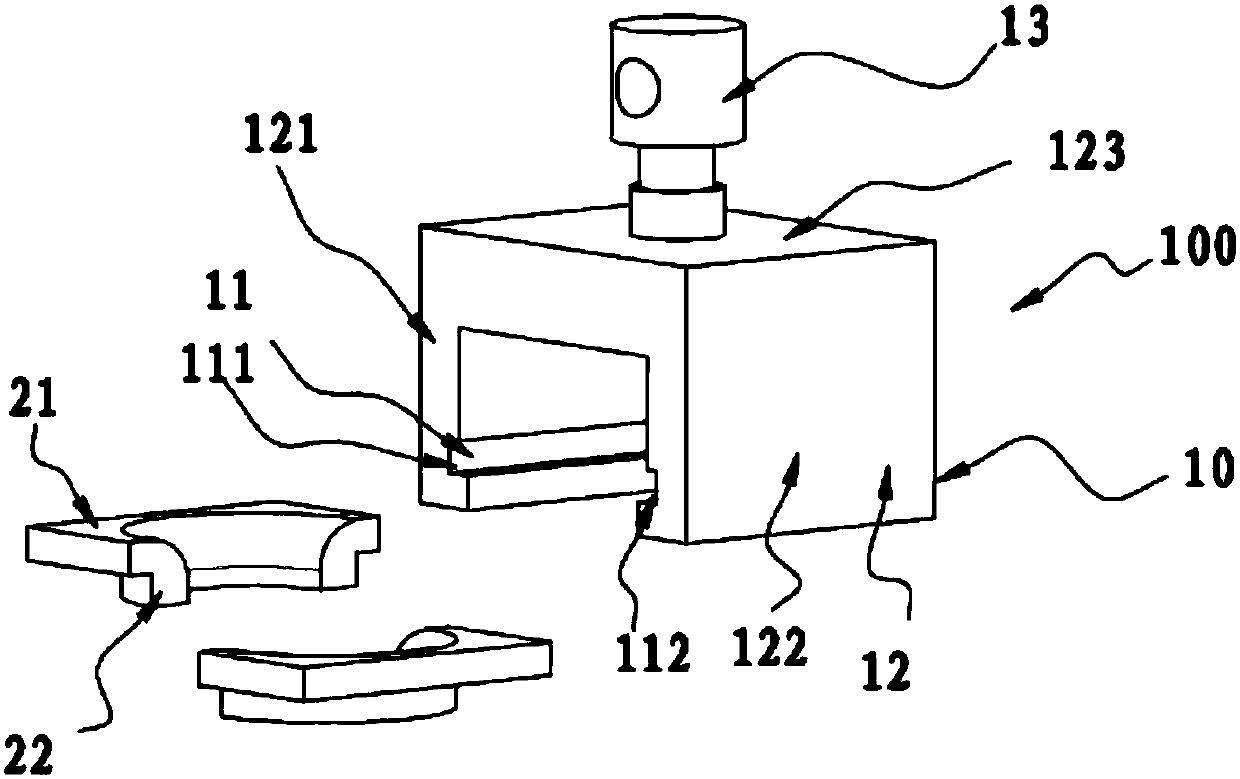
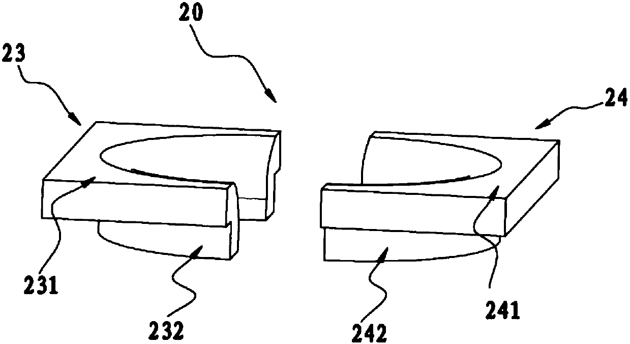
[0029] Such as figure 1 The clamp 100 shown is used to fix a sample and includes a base 10 and a splint 20 detachably connected to the base 10. The splint 20 includes a pushing portion 21 for pushing the sample and a resisting part 21. The wall surface of the clamping portion 22 connected to the pushing portion 21 is a smooth arc surface, and the wall surface of the clamping portion 22 matches the outer profile of the sample.

[0030] In this embodiment, the clamping portion 22 is a structure that directly fixes the sample, and the sample is fixed by the clampi...


PUM


Abstract

A clamp, a clamp pair and a stretching device are disclosed. The clamp is used for fixing a sample piece, and includes a base and a clamping plate detachably connected to the base. The clamping plateincludes an abutting and pushing part used for abutting and pushing the sample piece, and a clamping part connected to the abutting and pushing part. The wall surface of the clamping part is a smootharc surface, and is matched with the contour of the sample piece. As the wall surface of the clamping part is matched with the contour of the sample piece, the clamping part and the sample piece are tightly attached, and the clamp has high sample piece fixing stability. The clamping part has the smooth arc surface, thus increasing the contact area between the clamp and a stress part of the samplepiece, and ensuring uniform stress on the sample piece. In addition, the clamp also comprises the abutting and pushing part, and the abutting and pushing part abuts against the sample piece during a stretching test so as to indirectly fix the sample piece, thus facilitating sample piece stretching, and improving reliability of sample piece fixing by the clamp in a stretching process.

Description

technical field [0001] The invention relates to the field of tensile testing, more specifically, to a clamp, a pair of clamps and a tensile device. Background technique [0002] With the rise and rapid development of high and new technologies such as aerospace, electronic industry, and instrumentation, new requirements have been put forward for the use of materials. The continuous emergence of new materials, new structures, and new devices often requires the connection of dissimilar materials. Among them, the connection of ceramics and metals is widely used and very representative, so it has always been a hot topic in the field of theoretical and applied research at home and abroad. New structural ceramics have excellent properties such as high temperature resistance, corrosion resistance and wear resistance, but their plasticity is extremely poor and it is difficult to make large-scale or complex-shaped components. The best way to solve this problem is to use sealing techn...

Claims


Application Information

Patent Timeline
IPC IPC(8): G01N3/04
CPCG01N3/04G01N2203/0017G01N2203/04
Inventor 吕宏峰王小强邓传锦孙宇罗军刘焱
Owner CHINA ELECTRONICS PROD RELIABILITY & ENVIRONMENTAL TESTING RES INST THE FIFTH ELECTRONICS RES INST OF MIITCEPREI LAB
Why Eureka
Try Eureka