Check patentability & draft patents in minutes with Patsnap Eureka AI!

Contact finger assembly

A technology of contact fingers and components, which is applied in the direction of electrical components, high-voltage air circuit breakers, electric switches, etc., can solve the problems of high connection clearance requirements, inability to guarantee load consistency, and high production precision requirements, so as to ensure load consistency , reliable contact and good dynamic stability

Inactive Publication Date: 2018-02-16
宁波中迪机械有限公司
View PDF6 Cites 0 Cited by
  • Summary
  • Abstract
  • Description
  • Claims
  • Application Information

AI Technical Summary

Problems solved by technology

Although the connection method of the contact finger structure of the watch strap is low in cost, it has high requirements for the matching clearance of the connection, and it is difficult to assemble in actual construction
Another kind of plum blossom contact finger structure has slightly lower requirements on the fit clearance of the connection, but it cannot guarantee the consistency of the load on each contact finger, and the installation is difficult, and the production accuracy is high.

Method used


Image

  • Contact finger assembly

Examples


Embodiment Construction

[0017] The present invention will be further described below in conjunction with the accompanying drawings and specific embodiments.

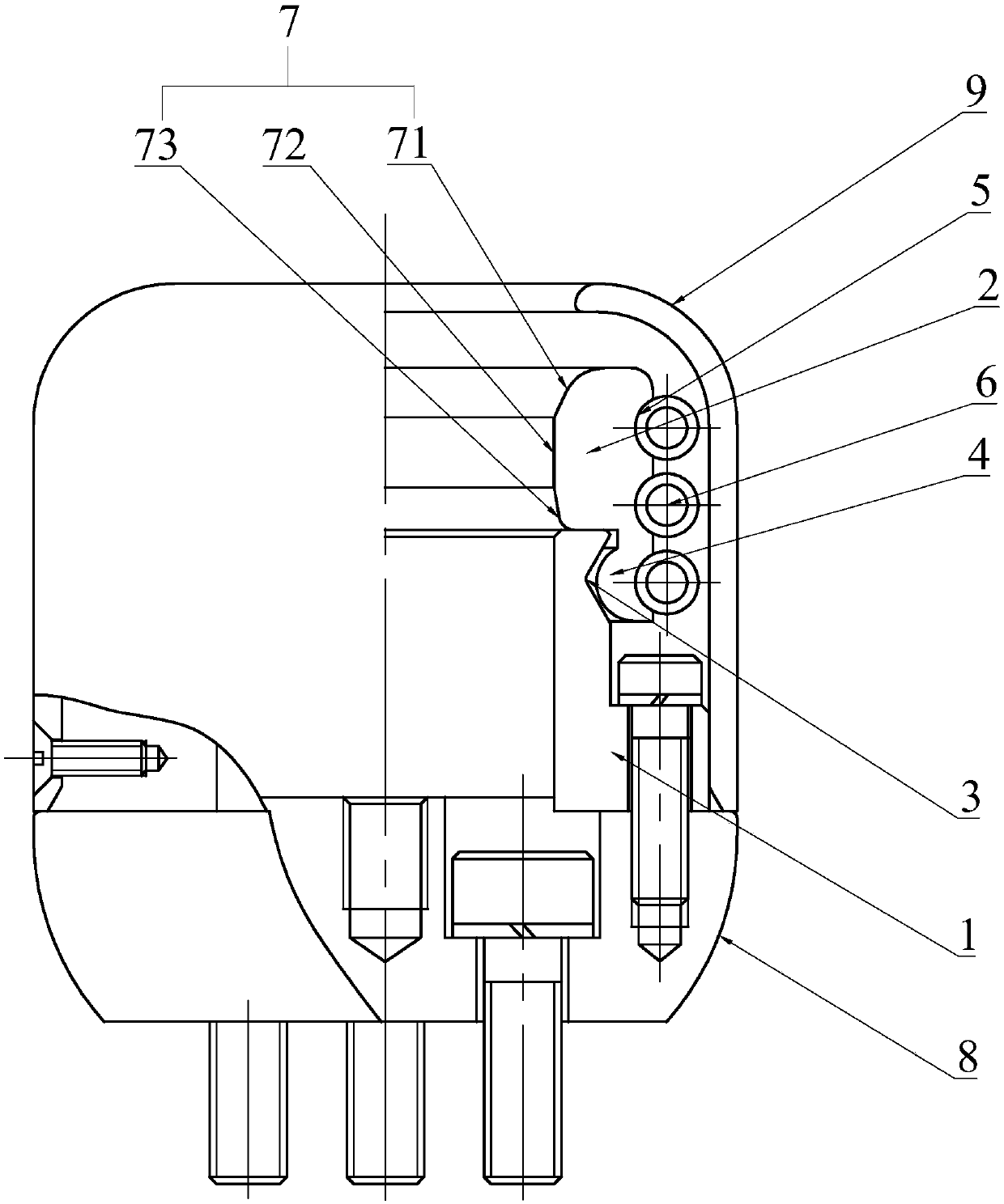
[0018] see figure 1 As shown, the contact finger 2 assembly of the present invention includes a contact finger 2 seat 1 and several contact fingers 2, the contact finger 2 seat 1 is tubular and the outer wall of the contact finger 2 seat 1 is provided with a limiting groove 53, the The contact finger 2 is arranged along the circumference of the contact finger 2 seat 1 and is slidably connected with the end of the contact finger 2 seat 1. One side of the contact finger 2 is provided with a limit block 4 that conflicts with the limit groove 53 and the other At least one groove 5 is provided on the side, and at least one ring spring 6 is also included. The ring spring 6 is matched with the groove 5 on each contact finger 2. When the conductive rod is inserted into the contact finger 2 assembly, the contact finger 2 is held by the spring Pressing ...


PUM


Abstract

The invention discloses a contact finger assembly. The contact finger assembly has load consistency on each contact finger, simple installation and relatively low production precision requirement; according to the key points of the technical scheme, a contact finger base is tubular and a limiting groove is formed in the outer wall of the contact finger base; the contact fingers are arranged in theperipheral direction of the contact finger base and are glidingly connected with the end part of the contact finger base; a limiting block propping against the limiting groove is arranged on one sideof each contact finger while at least one groove is formed in the other side; the contact finger assembly also comprises at least one annular spring; each annular spring is matched with the grooves in each contact finger; when a conductive rod is inserted in the contact finger assembly, the contact finger is pressed on the conductive rod by the corresponding spring; and by virtue of proper matching between the inner diameter of the contact finger assembly and the conductive rod, each contact finger and the corresponding conductive rod form contact of two lines, thereby obtaining reliable contact, and ensuring load consistency on each contact finger.

Description

technical field [0001] The invention relates to a contact finger assembly, more specifically to an electrical connection device of a gas-insulated metal-enclosed switch (GIS). Background technique [0002] The main function of the electrical connection device of the gas-insulated metal-enclosed switch (GIS) is to conduct the rated current and the instantaneous fault current in the main circuit. It has high requirements on the electrical and mechanical properties of the electrical connection, and its quality is good. Failure directly affects the reliability of GIS and the safe operation of the power grid. [0003] At present, the electrical connectors in domestic GIS equipment are usually connected by plum blossom contacts or strap contacts. Although the connection method of the contact finger structure of the strap is low in cost, it has high requirements on the matching clearance of the connection, and it is difficult to assemble in actual construction. Another kind of pl...

Claims


Application Information

Patent Timeline
IPC IPC(8): H01H33/02
CPCH01H33/025
Inventor 王重杰
Owner 宁波中迪机械有限公司
Features
  • R&D
  • Intellectual Property
  • Life Sciences
  • Materials
  • Tech Scout
  • Unparalleled Data Quality
  • Higher Quality Content
  • 60% Fewer Hallucinations
Learn More