Automatic detection equipment for producing battery

An automatic detection and battery technology, applied in secondary battery manufacturing, measuring electricity, measuring devices, etc., can solve problems such as battery failure and integration of production lines, and achieve the effect of avoiding missed detection, high degree of automation, and convenient assembly.

Inactive Publication Date: 2018-02-16
WUXI AOTU AUTOMATION TECH CO LTD
0 Cites 9 Cited by

AI-Extracted Technical Summary

Problems solved by technology

[0004] The object of the present invention is to provide a kind of automatic detection equipment for battery production, to solve the problem that the d...

Abstract

The invention discloses automatic detection equipment for producing a battery. The automatic detection equipment comprises a rack, wherein fixed frames are respectively arranged at two ends of the rack in a mutual symmetry manner; a detection rotating shaft is arranged on the inner wall, close to a rack, of the two fixed frames; a detection rotary table is arranged at one end, close to the outer walls of the fixed frames, of the detection rotating shaft; a reinspection rotary table is arranged at one end, close to the outer walls of the fixed frames, of the reinspection rotating shaft; an outlet rotary table is arranged at one end, close to the outer walls of the fixed frames, of an outlet rotating shaft; positioning grooves are formed in the outer wall of the detection rotary table; detection heads are arranged on the bottom surfaces inside the corresponding positioning grooves. The automatic detection equipment disclosed by the invention is convenient to assemble due to an uncomplicated structure and few components; the automatic detection equipment can be arranged at the unbroken position of a production process flow of the battery; a production line for integrated production and detection has high degree of automation; in addition, according to the automatic detection equipment disclosed by the invention, a formed battery is detected by adopting two detection tables, so that the detection efficiency is greatly ensured and leak detection is avoided.

Application Domain

Technology Topic

Image

  • Automatic detection equipment for producing battery
  • Automatic detection equipment for producing battery

Examples

  • Experimental program(1)

Example Embodiment

[0015] The technical solutions in the embodiments of the present invention will be clearly and completely described below in conjunction with the accompanying drawings in the embodiments of the present invention. Obviously, the described embodiments are only a part of the embodiments of the present invention, rather than all the embodiments. Based on the embodiments of the present invention, all other embodiments obtained by those of ordinary skill in the art without creative work shall fall within the protection scope of the present invention.
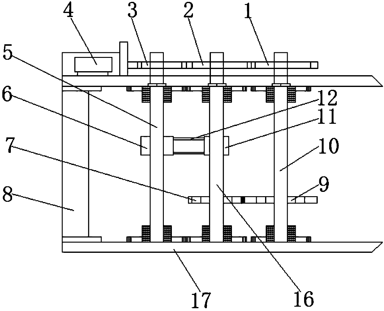
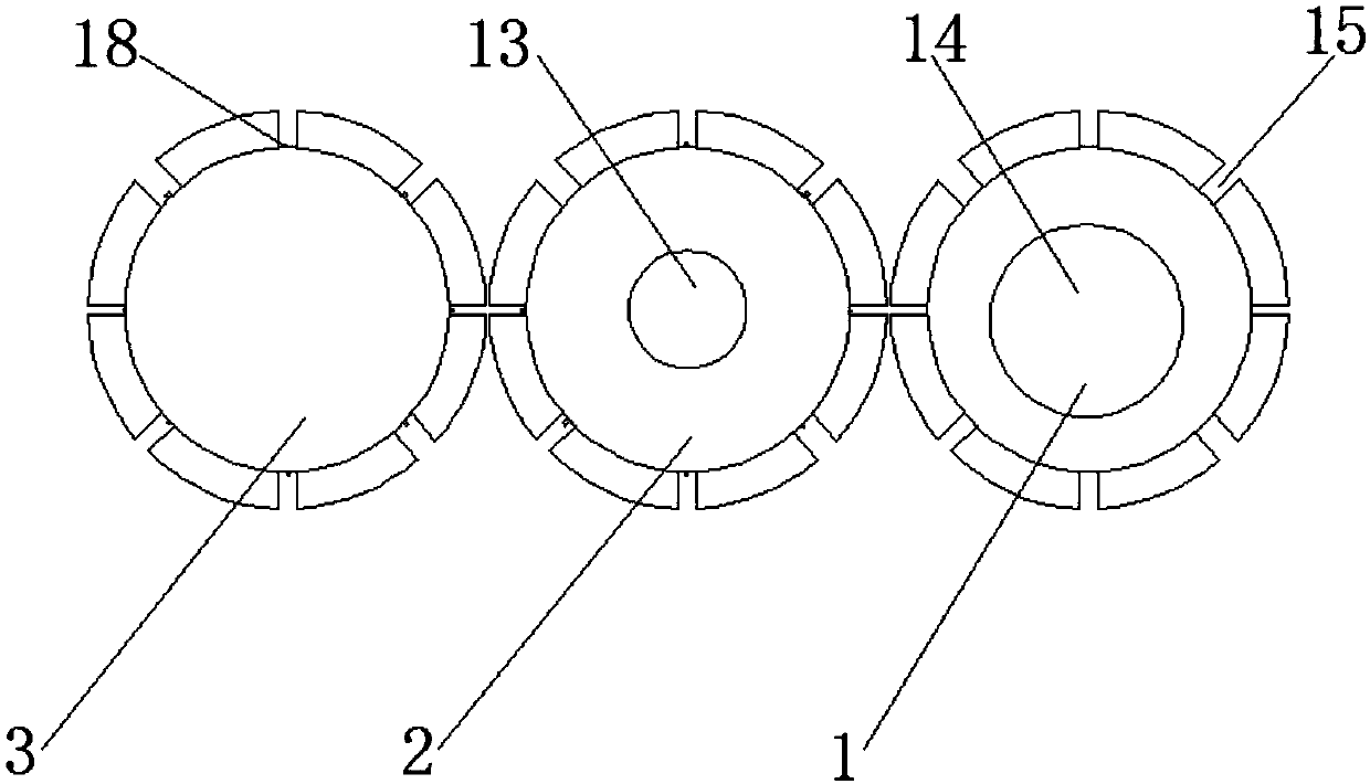
[0016] See Figure 1-2 , The present invention provides the following technical solutions: an automatic testing equipment for battery production, including a frame 8, the two ends of the frame 8 are symmetrically provided with a fixing frame 17, and two fixing frames 17 are arranged close to the inner wall of the frame 8. The detection shaft 5 is provided with a detection turntable 3 at one end of the detection shaft 5 close to the outer wall of the fixing frame 17, two fixing frames 17 are provided with a recheck shaft 16 close to the inner wall of the detection turntable 3, and the recheck shaft 16 is set close to one end of the outer wall of the fixing frame 17 There is a re-inspection turntable 2. The two fixing frames 17 are provided with an outlet shaft 10 close to the inner wall of the re-inspection shaft 16, and the outlet shaft 10 is provided with an outlet dial 1 at one end close to the outer wall of the fixing frame 17, and the middle position of the detection shaft 5 is provided with a follower The belt pulley 6 is provided with a rotating belt pulley 11 in the middle position of the rechecking shaft 16, a belt loop 12 is arranged on the outer wall of the rotating belt pulley 11, and a detecting shaft gear 7 is arranged on the outer wall of the rechecking shaft 16 close to the rotating belt pulley 11. The outer wall of the rotary shaft 10 close to the detection rotary gear 7 is provided with an outlet rotary shaft gear 9, the outer wall of the outlet rotary plate 1 is provided with a positioning groove 15, and the outlet rotary plate 1 is provided with a large electromagnet 14 inside, and the outer wall of the recheck rotary plate 2 is provided with a positioning groove 15, and a small electromagnet 13 is arranged inside the recheck turntable 2, a positioning groove 15 is arranged on the outer wall of the detection turntable 3, a battery conveying device 4 is arranged on the fixing frame 17 near the outer wall of the detection turntable 3, and the inner bottom surface of the positioning groove 15 A detection head 18 is provided.
[0017] In the present invention, preferably, the driven belt pulley 6 is connected to the rotating belt pulley 11 through a belt loop 12.
[0018] In order to keep the rotation speed consistent, in the present invention, preferably, the outlet shaft 10 and the recheck shaft 16 are geared in meshing connection.
[0019] In order to facilitate installation, the frame 8 and the fixing frame 17 are an integrated structure.
[0020] For the accuracy of detection, in the present invention, preferably, the detection head 18 and the small electromagnet 13 may form an electrical signal control connection.
[0021] For the accuracy of detection and the normal operation of detection, in the present invention, preferably, the small electromagnet 13 and the large electromagnet 14 may form an electrical signal control connection.
[0022] The working principle and use process of the present invention: After the present invention is installed, the two ends of the frame 8 are symmetrically provided with a fixing frame 17, and the two fixing frames 17 are provided with a detection shaft 5 near the inner wall of the frame 8, which is a detection disk To provide power, a detection turntable 3 is provided at one end of the detection shaft 5 close to the outer wall of the fixed frame 17, where the battery is tested for the first time, the two fixing frames 17 are close to the inner wall of the detection turntable 3, and a re-inspection shaft 16 is provided. One end of the outer wall of the fixing frame 17 is provided with a recheck turntable 2 where the battery is tested for the second time. The two fixing frames 17 are provided with an outlet shaft 10 close to the inner wall of the recheck shaft 16, and the outlet shaft 10 is provided with an end close to the outer wall of the fixing frame 17 Outlet turntable 1, the qualified battery comes out of the outlet turntable 1, the unqualified intermediate process is screened down, the middle position of the detection shaft 5 is provided with a driven belt pulley 6, and the middle position of the recheck shaft 16 is provided with a rotating belt pulley 11. A belt ring 12 is provided on the outer wall of the rotating belt pulley 11, a detection shaft gear 7 is provided on the recheck shaft 16 close to the outer wall of the rotating belt pulley 11, and an outlet shaft gear 9 is provided on the outlet shaft 10 close to the outer wall of the detection shaft gear 7. The outer wall of the exit turntable 1 is provided with positioning grooves 15, the inspection turntable 3 and the re-inspection turntable 2 are both provided with the same positioning grooves 15, and the exit turntable 1 is provided with a large electromagnet 14 inside, and the outer wall of the re-inspection turntable 2 is provided with positioning The inner wall of the recheck turntable 2 is provided with a small electromagnet 13. The large electromagnet 14 and the small electromagnet 13 can form electrical signals. The outer wall of the detection turntable 3 is provided with a positioning slot 15, and the fixing frame 17 is close to the detection turntable 3. The battery conveying device 4 is provided on the outer wall, and the detection head 18 is provided on the inner bottom surface of the positioning groove 15.
[0023] In the present invention, the device for moving the battery from the inspection turntable 3 to the re-inspection turntable 2 and from the re-inspection turntable 2 to the outlet turntable 1 is the prior art. The present invention is not shown in the figure and only needs to be moved by gap type grabbing.
[0024] Although the embodiments of the present invention have been shown and described, those of ordinary skill in the art can understand that various changes, modifications, and substitutions can be made to these embodiments without departing from the principle and spirit of the present invention. And variations, the scope of the present invention is defined by the appended claims and their equivalents.

PUM

no PUM

Description & Claims & Application Information

We can also present the details of the Description, Claims and Application information to help users get a comprehensive understanding of the technical details of the patent, such as background art, summary of invention, brief description of drawings, description of embodiments, and other original content. On the other hand, users can also determine the specific scope of protection of the technology through the list of claims; as well as understand the changes in the life cycle of the technology with the presentation of the patent timeline. Login to view more.

Similar technology patents

Snappingly assembled surf fins

InactiveUS7025645B1Easy to assembleWater sport boardsHydrodynamic/hydrostatic featuresEngineeringMechanical engineering
Owner:HSIEH KENG HSUN

Sectional shelf

InactiveUS20080116156A1Easy to assembleImproving connection mannerRacksFolding cabinetsCoupling
Owner:WON GU

Classification and recommendation of technical efficacy words

  • Easy to assemble
  • High degree of automation

Mahjong machine

Owner:德兴市永达娱乐设备有限公司

Full-automatic flexible assembly line of light emitting diode (LED) bulb lamp

InactiveCN102896494AIncreased reliability and automationHigh degree of automationAssembly machinesLight sourceStructure based
Owner:SHANGHAI RADIO EQUIP RES INST
Why Eureka
Try Eureka