Self-clamping insulated cable puncture clamp

A technology for insulating cables and puncture wire clips, applied in circuits, electrical components, conductive connections, etc., can solve problems such as poor waterproofing, loose and oxidized holding forces of the two glands, and achieve the effect of lowering temperature and facilitating clamping operations.

Active Publication Date: 2018-02-16
STATE GRID ZHEJIANG ELECTRIC POWER CO LTD QUZHOU POWER SUPPLY CO +2
View PDF8 Cites 1 Cited by
  • Summary
  • Abstract
  • Description
  • Claims
  • Application Information

AI Technical Summary

Problems solved by technology

However, when the existing insulation piercing wire clamp is installed, it is laborious to tighten the gland by bolts, especially when using an insulating rod for long-distance operation; in addition, with the prolongation of the use time and external effects, the two pressures will change. The cover's holding force is loose, resulting in poor waterproofing, poor contact between the puncture blade and the wire, severe oxidation, increased resistance, and obvious heat generation

Method used


Image

  • Self-clamping insulated cable puncture clamp
  • Self-clamping insulated cable puncture clamp
  • Self-clamping insulated cable puncture clamp

Examples


Embodiment 1

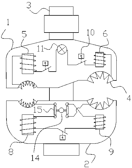
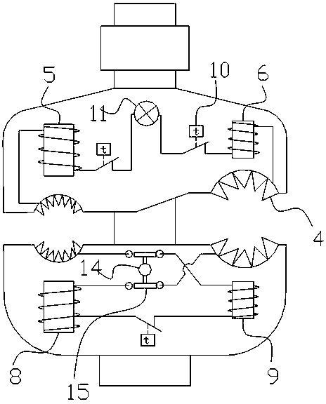
[0026] Such as figure 1 , 2 , 3, a self-clamping insulated cable puncture clamp, including the first gland 1 and the second gland 2, the fastening bolt 3 passing through the gland, and the clamps on both sides of the fastening bolt For the left and right card slots for clamping the cable, each card slot is composed of two half card slots opposite to each other on the first gland and the second gland, and a piercing blade 4 is arranged in the half card slot; A first left electromagnet 5 and a first right electromagnet 6 are respectively arranged above the left and right two draw-in slots on the gland. The piercing blades in the two draw-in slots are electrically connected, and the second gland is provided with a second left electromagnet 8 and a second right electromagnet corresponding to the first left electromagnet and the first right electromagnet on the first gland. 9. The second left electromagnet is connected in series with the second right electromagnet, and the two en...

Embodiment 2

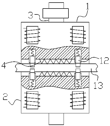
[0033] Such as Figure 4As shown, in the above, the bolts between the two glands are covered with springs, the springs are double-way memory alloy springs 16, and the two ends of the springs are electrically connected to the piercing blades of the left and right slots through wires. The spring is stretched at normal temperature, and it is supported between the two cover plates to open the two cover plates to facilitate the insertion of the wire into the slot; when the current passes through the spring, the temperature of the spring increases, causing the spring to contract, thereby facilitating Clamping of the two cover plates. The fastening bolt is a polished rod without thread. In order to facilitate the movement of the cover plate along the polished rod. During installation, pressurize the two glands to clamp the cable, and then rely on the electromagnetic force of the electromagnet to maintain the clamping force. When the puncture clamp needs to be removed, the current i...


PUM


Abstract

The invention provides a self-clamping insulated cable puncture clamp, relates to an insulated cable puncture clamp and aims at solving the problems that an insulated puncture clamp is strenuous in gland tightening and loose in clamping force in use in the prior art. The self-clamping insulated cable puncture clamp comprises oppositely arranged first gland and second gland, a fastening bolt, a left clamping groove and a right clamping groove, wherein the fastening bolt passes through the glands; the left clamping groove and the right clamping groove are located in two sides of the fastening bolt and are used for clamping cables; each clamping groove is formed by oppositely arranged two half clamping grooves located in the first gland and the second gland; puncture blades are arranged in each half clamping groove; a first left electromagnet and a first right electromagnet are arranged at the upper parts of the left clamping groove and the right clamping groove in the first gland separately and are connected in series; and the second gland is provided with iron blocks or magnets corresponding to the electromagnets on the first gland. According to the self-clamping insulated cable puncture clamp, the clamping force of the two glands is automatically increased after the puncture blades are in contact with wires, and the clamping force is always kept in use.

Description

technical field [0001] The invention belongs to the technical field of electrical equipment, and relates to an insulating cable puncture clamp. Background technique [0002] The insulation piercing clamp is mainly composed of two split glands, piercing blades, bolts passing through the two glands, and torque nuts. When the cable needs to be branched or connected, after determining the branch position of the main line, use a socket wrench to twist the torque nut on the clamp. During the process, the contact blade will pierce the cable insulation layer and contact the conductor, and the gasket ring will press the cable and be punctured. Around the position, when the torque reaches the set value, the nut torque mechanism falls off, and the main line and branch line are connected. It has the characteristics of easy installation, low cost, safety, reliability and maintenance-free. The cable branch can be made without cutting the main cable or stripping the insulation layer of t...

Claims


Application Information

Patent Timeline
Patent Type & Authority Applications(China)
IPC IPC(8): H01R4/2407H01R4/2408H01R4/247H01R4/01H01R11/05H01R13/641H01R13/62H01R13/713H01R13/717
CPCH01R4/01H01R4/247H01R11/05H01R13/6205H01R13/641H01R13/7137H01R13/7175
Inventor 方雄伟钱宾方嘉伟徐辉颜明华刘利平童雄伟徐小峰张越夏耀春韩统
Owner STATE GRID ZHEJIANG ELECTRIC POWER CO LTD QUZHOU POWER SUPPLY CO
Why Eureka
Try Eureka