
Transformer DC magnetic bias suppression device, method and transformer system

A DC bias suppression and suppression device technology, applied in the direction of emergency protection circuit devices, electrical components, etc., can solve the problems of transformer safety grounding, high cost, high installation space requirements, etc., to achieve the suppression of effective grounding, suppression of DC bias, applicable Good range of effects

Pending Publication Date: 2018-02-16
ECONOMIC TECH RES INST OF STATE GRID ANHUI ELECTRIC POWER +1
View PDF0 Cites 3 Cited by
  • Summary
  • Abstract
  • Description
  • Claims
  • Application Information

AI Technical Summary

Problems solved by technology

To connect a resistor in series with the neutral line of the transformer, it is necessary to select a current-limiting resistor according to the actual operating conditions, and the operation is more complicated.
Appropriate capacitors are connected in series at the neutral point of the transformer. The capacitors used have high withstand voltage requirements, high cost and high installation space requirements, and parallel bypass protection devices are required; transformer safety grounding problems may occur, affecting grid fault diagnosis and insulation coordination.
The current injection method requires undercompensation, which is not suitable for actual operation

Method used


Image

  • Transformer DC magnetic bias suppression device, method and transformer system
  • Transformer DC magnetic bias suppression device, method and transformer system
  • Transformer DC magnetic bias suppression device, method and transformer system

Examples


Embodiment Construction

[0023] The present invention will be further described below in conjunction with the accompanying drawings and specific embodiments.

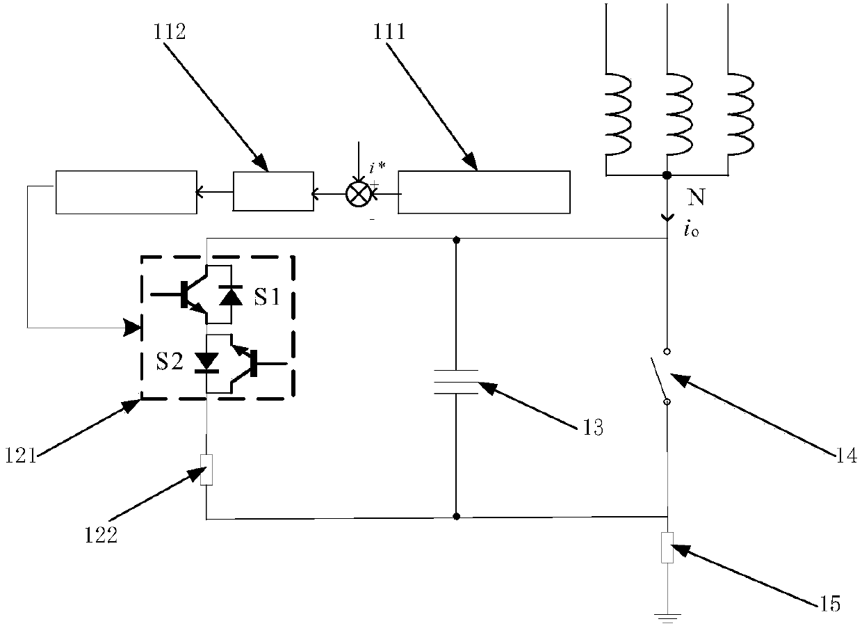
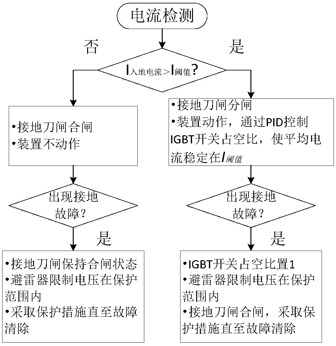
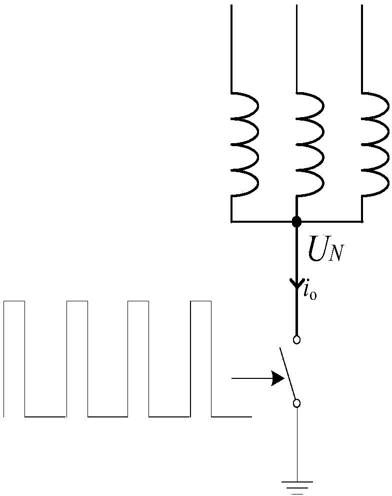
[0024] Such as Figure 1 to Figure 5 As shown, a transformer DC bias suppression device includes a detection control unit, a suppression unit, a lightning rod 13 , a knife switch 14 and a first resistor 15 . The detection control unit is connected to the suppression unit; the suppression unit, the lightning rod 13, and the knife switch 14 are connected in parallel, and the neutral point of the transformer is first connected in series with the parallel suppression unit, the lightning rod 13, and the knife switch 14, and then connected in series with the first resistor 15, and then grounded.

[0025] The detection control unit includes a voltage and current measurement and control module 111 and a PID control module 112 ; the voltage and current measurement and control module 111 is connected to the suppression unit through the PID control module...


PUM


Abstract

The invention provides a transformer DC bias suppression device, which includes a detection control unit, a suppression unit, a lightning rod, a knife switch and a first resistor; the detection control unit is connected to the suppression unit; the neutral point of the transformer is connected to the suppression unit in parallel , lightning rod, knife switch, and then the first resistor in series, and then grounded. A suppression method applied to the suppression device and a transformer system comprising the suppression device or comprising the suppression method are also provided. The invention has the beneficial effect of applying a direct-current bias scheme in which a wide bandgap semiconductor device SiC IGBT is combined with a resistor in series. It is proposed to use a semiconductor switch as a DC blocking device. Under the condition of ensuring the effective grounding of the transformer, the average grounding current is maintained within a reasonable threshold to achieve the effect of suppressing the DC bias of the transformer. It can effectively ground the suppression device, withstand voltage level, Find a better balance in several aspects of flexibility and expanding the scope of application.

Description

technical field [0001] The invention relates to a DC bias suppression method, in particular to a transformer DC bias suppression device, method and transformer system. Background technique [0002] HV / UHV DC transmission has the advantages of large capacity, low loss, and long transmission distance. With the rapid growth of my country's economy, the development of DC transmission technology is in the stable operation of long-distance power transmission, new energy grid integration and consumption, and AC interconnection grid. Maintenance and other aspects play a vital role. However, the single-pole return operation mode of the DC transmission project will increase the ground potential near the ground electrode, and generate a potential difference between different substations, resulting in the risk of DC bias in the transformer, endangering the normal operation of the power system, and also causing the transformer to heat up. Noise, resonance and other problems. Therefore, ...

Claims


Application Information

Patent Timeline
Patent Type & Authority Applications(China)
IPC IPC(8): H02H7/04
CPCH02H7/04
Inventor 马静杨娜陈煜文习山潘卓洪刘晨蕾
Owner ECONOMIC TECH RES INST OF STATE GRID ANHUI ELECTRIC POWER
Learn More