Driver adjustment circuit

A technology for regulating circuits and drivers, applied in logic circuits, electrical components, electronic switches, etc., can solve problems such as inaccurate range values ​​and difficult control of range values, and achieve the effects of wide delay range, simple design, and wide sensing range

Pending Publication Date: 2018-02-16
HUIZHOU CITY YUAN SHENG TECH CO LTD
View PDF0 Cites 0 Cited by
  • Summary
  • Abstract
  • Description
  • Claims
  • Application Information

AI Technical Summary

Problems solved by technology

At present, the current method of adjusting the sensor by the existing driver is to adjust the voltage through the direct output of the MCU (Microcontroller Unit, MCU for short). However, on the one hand, this method is not easy to control the output range value. The output range value is also inaccurate

Method used


Image

  • Driver adjustment circuit
  • Driver adjustment circuit
  • Driver adjustment circuit

Examples


Embodiment 1

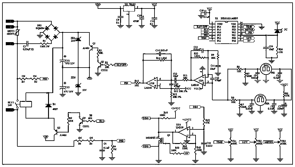
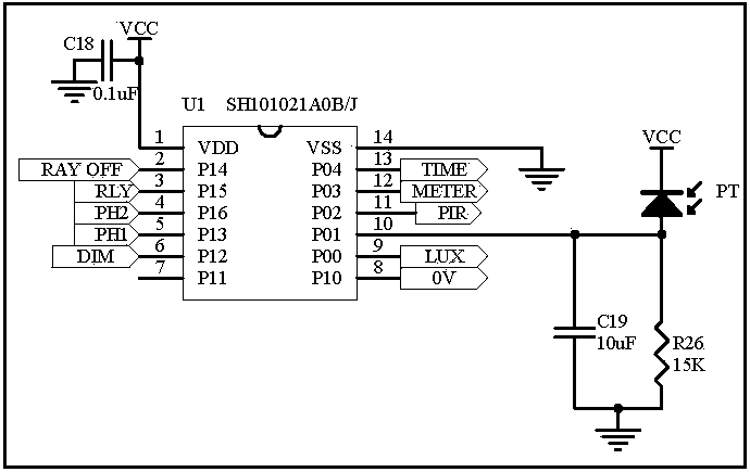
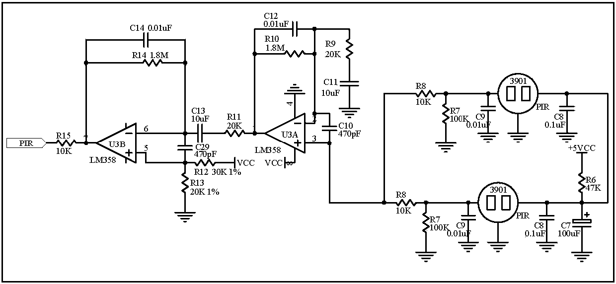
[0031] A driver regulation circuit, including an MCU module, a human body sensing module, a light control module, a power supply module, a PWM (PulseWidth Modulation, pulse width modulation, PWM for short) integration module, an output module, a relay control module, a power reduction module, and a delay module. Time module and human body sensing range adjustment module, human body sensing module, light control module, power supply module, PWM integration module, output module, relay control module, power reduction module, delay module and human body sensing range adjustment module are all connected to the MCU module , the MCU module includes a micro central processing unit; the PWM integral module includes a resistor R42 and a capacitor C42, the resistor R42 and the capacitor C42 are connected in series, and one end of the capacitor C42 is grounded; the output module includes an operational amplifier U5A, a resistor R43, a resistor R44, a resistor R45 and a MOSFET tube Q5, the...

Embodiment 2

[0039] Such as Figure 10 The difference between Embodiment 1 and Embodiment 2 is that the output module includes an operational amplifier U5A, a resistor R43, a resistor R44, a resistor R45, and a triode Q5. The C pole of the triode Q5 is grounded, and the B pole of the triode Q5 is connected to the The output terminal of the operational amplifier U5A, the C pole of the triode tube Q5 is connected in series with the resistor R45, one end of the resistor R45 is connected to +12VCC, the + terminal of the operational amplifier U5A is connected to +12VCC, the - terminal of the operational amplifier U5A is grounded, and the resistor R44 is connected in parallel at the - terminal of the operational amplifier U5A and the output terminal of the operational amplifier U5A. Other circuit designs are the same as in Embodiment 1. The reason for this setting is that the triode can guarantee the output voltage is 1V-10V, while the output voltage is 0-10V if the MOSFET is used.

Embodiment 3

[0041] The difference between Embodiment 3 and Embodiment 1 and Embodiment 2 is: Embodiment 3 does not have a relay control module, and the others are the same as Embodiment 1. Not setting the relay control module is to reduce the cost on the one hand, and to save more power on the other hand, and the circuit will be simpler.


PUM


Abstract

The invention provides a driver adjustment circuit, and the circuit comprises an MCU module, a human body induction module, a light control module, a power module, a PWM integration module, an outputmodule, a relay control module, a power consumption reduction module, a time delay module and a human body induction range adjustment module. The human body induction module, the light control module,the power module, the PWM integration module, the output module, the relay control module, the power consumption reduction module, the time delay module and the human body induction range adjustmentmodule are all connected with the MCU module, and the MCU module comprises a central microprocessor. The circuit provided by the invention can guarantee that a voltage value outputted by a driver is stable, and the range of the outputted voltage is specific.

Description

technical field [0001] The invention relates to the field of drivers, in particular to a driver regulation circuit. Background technique [0002] The driver is the driving hardware for driving certain types of equipment, and is widely used in many fields. The driver of this application is mainly used in sensors, and the corresponding output of the driver is adjusted through the input of the sensor, and then the brightness of the lamp is controlled. At present, the current method of adjusting the sensor by the existing driver is to adjust the voltage through the direct output of the MCU (Microcontroller Unit, MCU for short). However, on the one hand, this method is not easy to control the output range value. The output range value is also not accurate. Contents of the invention [0003] In order to solve the above problems, the object of the present invention is to provide a driver regulation circuit, which can ensure that the output voltage value of the driver is stable, ...

Claims


Application Information

Patent Timeline
IPC IPC(8): H03K17/284H03K19/00H03K7/08
CPCH03K7/08H03K17/284H03K17/302H03K19/0013
Inventor 蔡艳清曾祥春王文周小捷
Owner HUIZHOU CITY YUAN SHENG TECH CO LTD
Why Eureka
Try Eureka