Rubber tapping machine and rubber tapping method

A rubber tapping machine and rubber tapping technology, which is applied in forestry, application, agriculture, etc., can solve the problems of guide rail shaking and deformation, poor tapping precision, and insufficient strength of flat and long guide rails, and achieve the effect of reducing the arm of force and solving the effect of high labor intensity

Pending Publication Date: 2018-02-23
NINGBO CIHEVEA TECH CO LTD
View PDF10 Cites 30 Cited by
  • Summary
  • Abstract
  • Description
  • Claims
  • Application Information

AI Technical Summary

Problems solved by technology

[0005] (1) The mechanism for fixing the tree is unrealistic. In the process of tapping rubber, the relative force between the mobile module and the tree can reach tens of kilograms, and the two-point fixation on one side cannot satisfy the balance of forces in all directions during the rubber tapping process.
[0006] (2) The vector superposition movement in the tapping process is controlled by two stepping motors, which has the hidden danger of poor tapping precision. The distance between the two tappings is very small, and there may be discrepancies between the two motors in the process of cooperation. Synchronous situation, so it is very unstable. If there is a deviation at the beginning of cutting, the final cutting point position of the two knives will have a large deviation, which will not only hurt the tree, but also affect the output
[0008] (4) During the cutting process, the cutting depth of the knife cannot be adjusted in real time according to the shape of the tree
Because the shape of the tree is uncertain, sometimes raised and sometimes sunken, this patent pre-adjusts the constant cutting depth according to the dial. In reality, if it encounters a sunken place, the knife of the device cannot cut to the bark. On the contrary, when it encounters a raised place, the knife will cut deeply and hurt the tree.
[0009] (5) In the process of circular motion around the tree, the stepper motor can only control the movement of the upper trolley, but cannot control the movement of the driven trolley on the lower guide rail. The impact may not be obvious during the no-load process, but in the cutting process At this time, the middle tool will bring resistance to the movement of the whole machine. At this time, the sliders on the upper and lower guide rails will not be synchronized. This phenomenon will cause the equipment to not work normally at all, or even directly destroy the equipment.
[0011] (1) The rotation of the lead screw drives the slide

Method used


Image

  • Rubber tapping machine and rubber tapping method
  • Rubber tapping machine and rubber tapping method
  • Rubber tapping machine and rubber tapping method

Examples


Embodiment 1

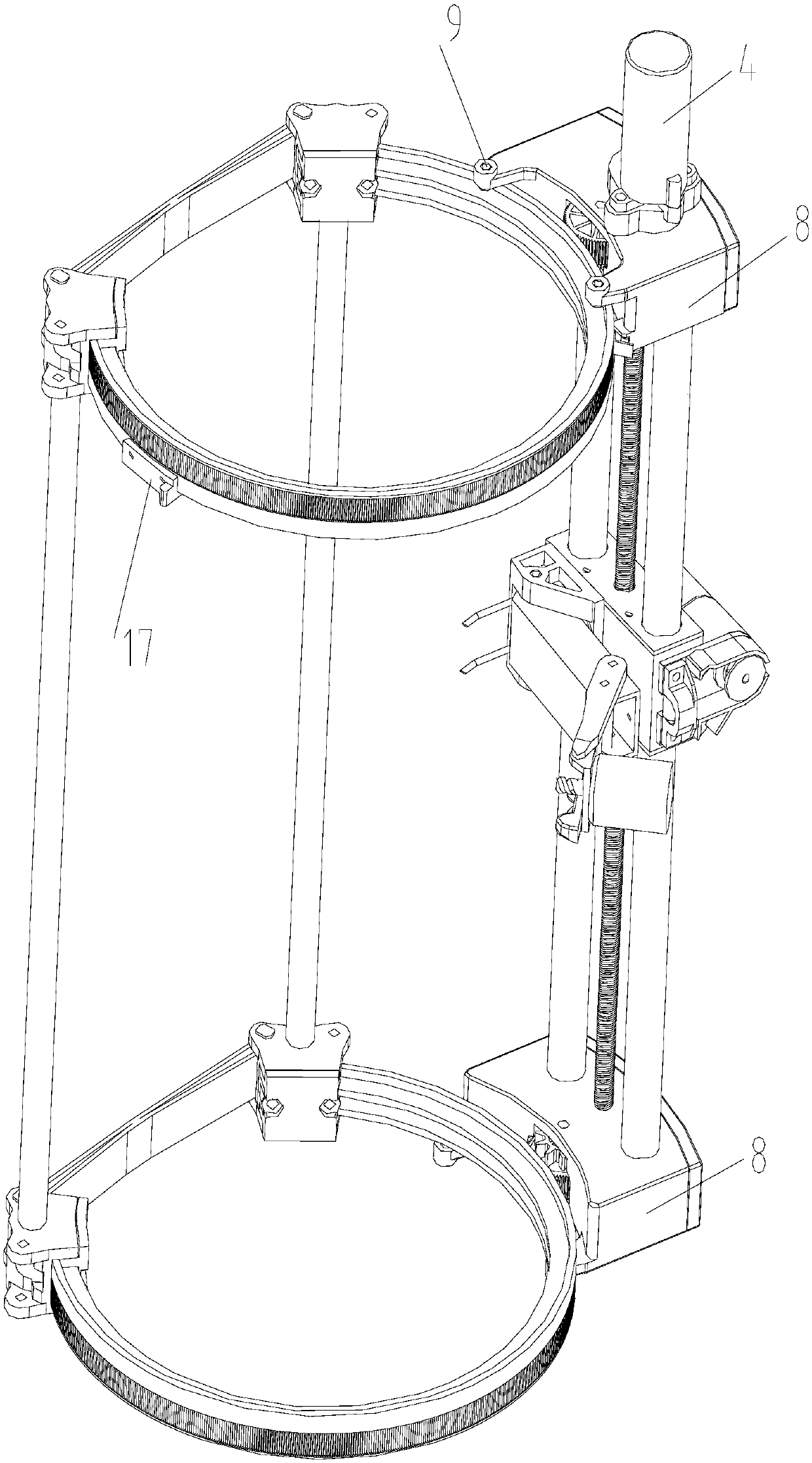
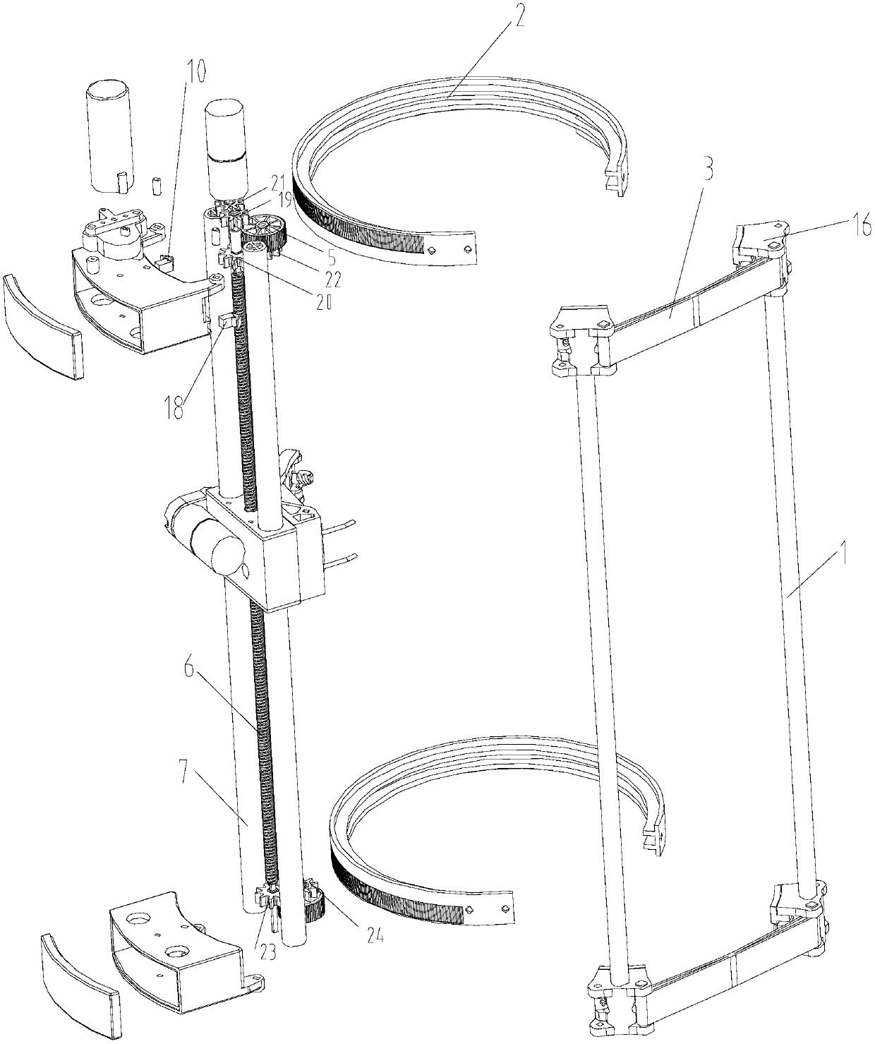
[0052] Example 1, such as Figure 1-2 As shown, this embodiment discloses a rubber tapping machine, the rubber tapping machine includes two support rods 1, one side of the support rods 1 is connected by a soft guide rail 2, and the other side is connected by a tightening belt 3, And the soft guide rail is opposite to the tightening belt on the opposite side; in this embodiment, the support rod is made of aluminum rod with light weight and high strength, and the soft guide rail is made of rubber guide rail with excellent strength and elasticity. Materials such as PVC, PU, ​​and elastic steel can be selected. The rubber tapping machine also includes a knife rest assembly with a motor 4. The motor is a geared motor. One is installed at the upper and lower ends of the knife rest assembly and can be mounted along the soft guide rail 2. The crawler wheel 5 that rolls on the outside, in addition, a lead screw 6 and more than one fixed rod 7 are installed vertically in the tool rest a...


PUM


Abstract

The invention discloses a rubber tapping machine and a rubber tapping method. The rubber tapping machine comprises support rods, a knife rest assembly and a rubber tapping knife assembly. A side of one of the support rods is connected with a side of the other support rod by flexible guide rails, the other side of each support rod is connected with the other side of the other support rod by tightening belts, and the flexible guide rails are opposite to the tightening belts on the sides opposite to the flexible guide rails; the knife rest assembly is provided with a motor, two track wheels capable of rolling along the outer sides of the flexible guide rails are mounted at the upper end and the lower end of the knife rest assembly, a lead screw and more than one fixing rod are further mountedin the knife rest assembly along the vertical directions, and the track wheels and the lead screw can be driven by the motor in the knife rest assembly to rotate. The rubber tapping machine and the rubber tapping method have the advantages that labor can be replaced by automatic machinery, accordingly, rubber can be automatically tapped from rubber trees in an unmanned manner, and the problems ofhigh labor intensity of manual rubber tapping and insufficient fineness of manual rubber tapping can be solved to the greatest extent.

Description

technical field [0001] The invention relates to the field of agricultural machinery, in particular to a rubber tapping machine and a tapping method for cutting rubber tree bark in this field. Background technique [0002] Since humans discovered that natural rubber can be collected from rubber trees, the method of making rubber bark to form rubber slides has always been cutting with a manual hand-held rubber tapping knife; although electric rubber tapping knives have appeared in modern times, manual hand-held operation is still required. [0003] Chinese invention patent application CN104429813A discloses a rubber tapping machine, which includes a tree-tying fixed frame and two ring-shaped planetary gear casings installed on the upper and lower ends of the tree-tying fixed frame respectively, and a vector moving tool rest assembly is set between the two planetary gear casings; The gear shaft is set on the moving knife rest assembly, and the motor and the rubber tapping knife...

Claims


Application Information

Patent Timeline
IPC IPC(8): A01G23/10
CPCA01G23/10
Inventor 许振昆吴纪营张兴明
Owner NINGBO CIHEVEA TECH CO LTD
Why Eureka
Try Eureka