
Rubber tapping machine and rubber tapping method

A rubber tapping machine and rubber tapping technology, applied in forestry, application, agriculture, etc., can solve problems such as instability, influence of glue, vibration and deformation of guide rails, etc., and achieve the effects of improving stability, ensuring continuity, and reducing the force arm

Pending Publication Date: 2020-11-24
NINGBO CIHEVEA TECH CO LTD
View PDF12 Cites 7 Cited by
  • Summary
  • Abstract
  • Description
  • Claims
  • Application Information

AI Technical Summary

Problems solved by technology

[0005] (1) The mechanism for fixing the tree is unrealistic. In the process of tapping rubber, the relative force between the mobile module and the tree can reach tens of kilograms, and the two-point fixation on one side cannot satisfy the balance of forces in all directions during the rubber tapping process.
[0006] (2) The vector superposition movement in the tapping process is controlled by two stepping motors, which has the hidden danger of poor tapping precision. The distance between the two tappings is very small, and there may be discrepancies between the two motors in the process of cooperation. Synchronous situation, so it is very unstable. If there is a deviation at the beginning of cutting, the final cutting point position of the two knives will have a large deviation, which will not only hurt the tree, but also affect the output
[0008] (4) During the cutting process, the cutting depth of the knife cannot be adjusted in real time according to the shape of the tree
Because the shape of the tree is uncertain, sometimes raised and sometimes sunken, this patent pre-adjusts the constant cutting depth according to the dial. In reality, if it encounters a sunken place, the knife of the device cannot cut to the bark. On the contrary, when it encounters a raised place, the knife will cut deeply and hurt the tree.
[0009] (5) In the process of circular motion around the tree, the stepper motor can only control the movement of the upper trolley, but cannot control the movement of the driven trolley on the lower guide rail. The impact may not be obvious during the no-load process, but in the cutting process At this time, the middle tool will bring resistance to the movement of the whole machine. At this time, the sliders on the upper and lower guide rails will not be synchronized. This phenomenon will cause the equipment to not work normally at all, or even directly destroy the equipment.
[0011] (1) The rotation of the lead screw drives the slider on it to move down, but the flat and long track cannot ensure that the slider on the polished rod on the other side of the track also moves downward by the same distance, so it cannot guarantee that the thickness of the bark cut by each knife is the same uniform
[0012] (2) In the process of returning to the initial position after cutting once, there is no knife retracting mechanism to retract the knife, and the knife always touches the glue line just cut, which will affect the glue flow
[0013] (3) Using one-sided blade spiral downward cutting or double-sided blade reciprocating cutting will affect the glue flowing down along the cut
[0014] (4) The guide rail will be twisted after spiraling, and the angle between the flat guide rail surface and the horizontal plane will deviate, which will affect the consistency of the cutting direction of the tool on the guide rail, and the angle of the cut surface relative to the horizontal plane will also be unstable
[0015] (5) The anti-deformation strength of the flat and long guide rail is not enough. During the operation of the traveling mechanism, the guide rail will vibrate and deform, and the cutting trajectory will be different each time due to the deformation of the guide rail.
[0016] (6) The knife is rigidly connected to the walking mechanism, and the knife cannot rotate relative to the secant direction, that is, there is no structure similar to the wrist, and the knife cannot be adjusted on different tree surfaces so that the knife head always rushes to the center of the tree. making it impossible to maintain a consistent depth of cut
[0017] (7) There is only one point of contact between the limit rod and the trunk, and the guidance and limit are not enough. The knife is easily stuck on the pit or small tree burl on the trunk
[0018] Therefore, the rubber tapping machine disclosed in this patent application is difficult to achieve uniform and stable cutting depth, cutting thickness and cutting track.

Method used


Image

  • Rubber tapping machine and rubber tapping method
  • Rubber tapping machine and rubber tapping method
  • Rubber tapping machine and rubber tapping method

Examples


Embodiment 1

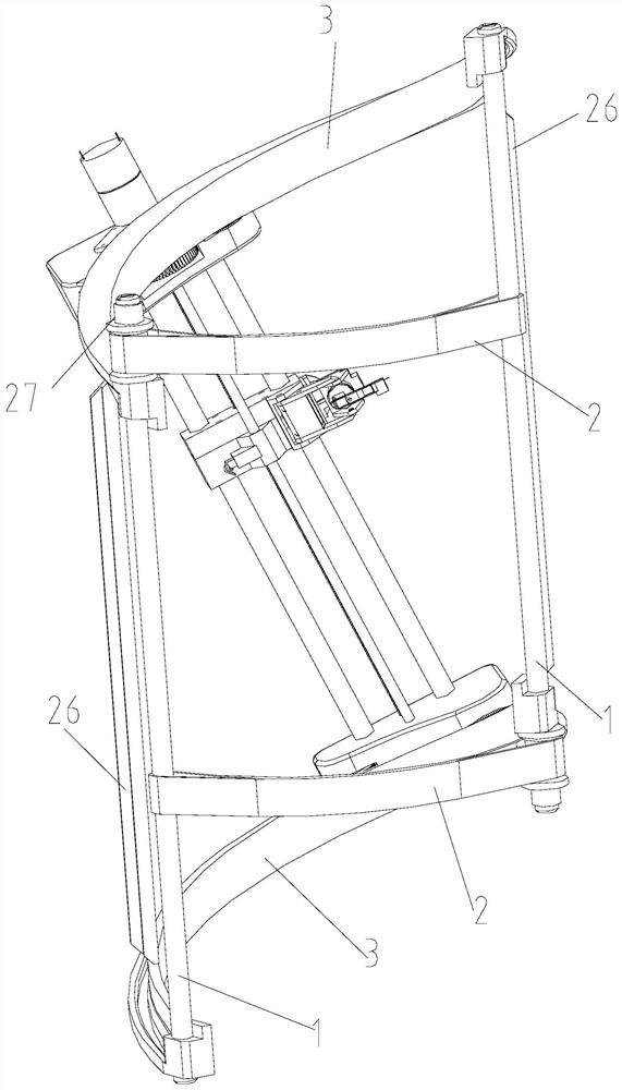
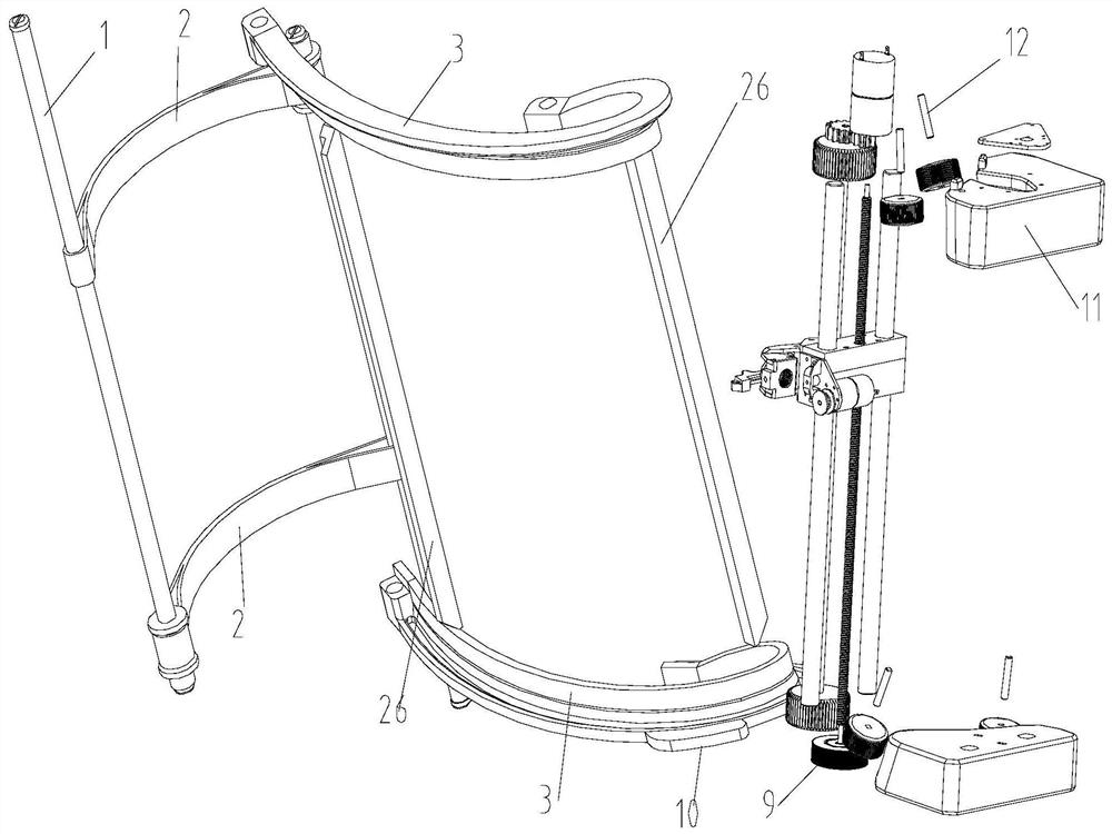
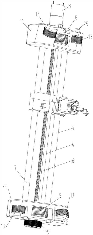
[0052] Example 1, such as Figure 1-5 As shown, this embodiment discloses a rubber tapping machine, the rubber tapping machine includes two supporting steel pipes 1, one side of the two supporting steel pipes 1 is connected by a strap 2, and the other side is connected by two upper and lower spiral guide rails. 3 are connected, and the spiral guide rail is opposite to the strap position on the opposite side, the spiral guide rail 3 can be made of rubber and the cross section is nearly L-shaped; the rubber tapping machine in this embodiment also includes a knife rest assembly with a motor 8 , the upper and lower ends of the power steel shaft 4 of the tool rest assembly are respectively equipped with a power wheel 5 that can roll along the spiral guide rail. The fixed rod 7, the above-mentioned power wheel 5 is driven to rotate by the motor 8 installed on the tool holder assembly, the lower end of the screw 6 is installed with the lowering roller 9 through a one-way bearing, and...


PUM


Abstract

The invention discloses a rubber tapping machine and a rubber tapping method. The rubber tapping machine comprises two supporting steel pipes, wherein one sides of the two supporting steel pipes are connected through binding belts, the other sides of the two supporting steel pipes are connected through an upper spiral guide rail and a lower spiral guide rail, and the positions of the spiral guiderails are opposite to the positions of the binding belts on the opposite sides of the spiral guide rails; the rubber tapping machine further comprises a knife rest assembly with a motor and a limit switch; the upper end and the lower end of a power steel shaft of the knife rest assembly are provided with power wheels capable of rolling along the spiral guide rails respectively; in addition, the knife rest assembly is further provided with a lead screw and more than one fixing rod in the vertical direction; the upper end and the lower end of the knife rest assembly penetrate through the lead screw and the fixing rod to be provided with main machine shells respectively; the main machine shells are clamped in grooves of the spiral guide rails; guide roller shafts are arranged in the main machine shells; guide rollers are arranged on the corresponding guide roller shafts; and the rubber tapping machine further comprises a rubber tapping knife assembly. According to the rubber tapping machine, manual work is replaced with automatic machinery, unmanned automatic rubber tapping of a rubber tree is achieved, and the problems that the labor intensity of manual rubber tapping is large and manual rubber tapping is not refined enough are solved to the maximum extent.

Description

technical field [0001] The invention relates to the field of agricultural machinery, in particular to a rubber tapping machine and a tapping method for cutting rubber tree bark in this field. Background technique [0002] Since humans discovered that natural rubber can be collected from rubber trees, the method of making rubber bark to form rubber slides has always been cutting with a manual hand-held rubber tapping knife; although electric rubber tapping knives have appeared in modern times, manual hand-held operation is still required. [0003] Chinese invention patent application CN104429813A discloses a rubber tapping machine, which includes a tree-tying fixed frame and two ring-shaped planetary gear casings installed on the upper and lower ends of the tree-tying fixed frame respectively, and a vector moving tool rest assembly is set between the two planetary gear casings; The gear shaft is set on the moving knife rest assembly, and the motor and the rubber tapping knife...

Claims


Application Information

Patent Timeline
Patent Type & Authority Applications(China)
IPC IPC(8): A01G23/12A01G23/10
CPCA01G23/12A01G23/10
Inventor 许振昆吴纪营张兴明
Owner NINGBO CIHEVEA TECH CO LTD
Learn More