
Glass chip clearing device used for glass forming machine

A cleaning device and molding machine technology, applied in the direction of cleaning method, cleaning method and utensils, chemical instruments and methods using gas flow, etc., can solve the problems of unsatisfactory efficiency, unsatisfactory, low efficiency, etc., to improve blowing efficiency , easy maintenance and maintenance, simple structure

Inactive Publication Date: 2018-02-23
SHANDONG PHARMA GLASS
View PDF0 Cites 0 Cited by
  • Summary
  • Abstract
  • Description
  • Claims
  • Application Information

AI Technical Summary

Problems solved by technology

[0002] At present, in order to reduce the problem of glass shavings produced by cold cutting glass processing, people have devised vacuum suction devices and compression blowing devices to eliminate the defect of glass shavings. The equipment currently on the market can be broken The crumb rate has dropped by about 50%, but it is still not ideal;
[0003] This efficiency is indeed not ideal, but the main equipment is vacuum equipment and air compressor equipment. The low efficiency has nothing to do with this main equipment. It is mainly due to the design of the suction head and blower head of the glass debris removal device, so it needs to be designed in this way. A reasonable suction head and blow-off head

Method used


Image

  • Glass chip clearing device used for glass forming machine
  • Glass chip clearing device used for glass forming machine
  • Glass chip clearing device used for glass forming machine

Examples


Embodiment 1

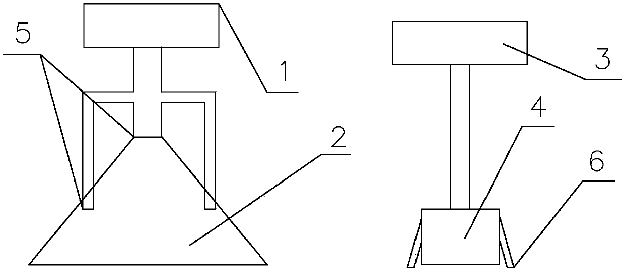
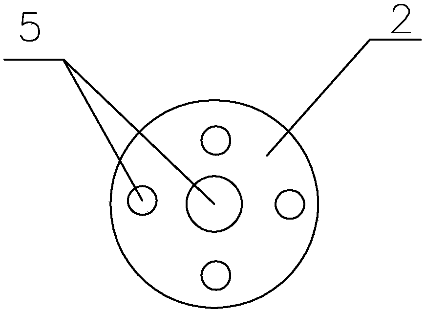
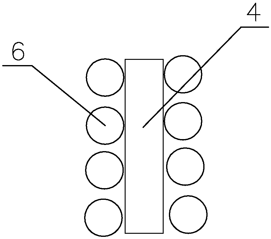
[0023] Such as Figure 1~3 As shown, the present invention comprises: vacuum suction device and compression blow-off device, and vacuum suction device comprises vacuum pump 1 and suction head 2, and compression blow-off device comprises compressor 3 and blow-off head 4, and described suction head 2 is a conical structure, five suction pipes 5 are arranged under the conical structure, and the suction pipes 5 are all connected to the vacuum pump 1 through pipelines;

[0024] A suction pipe 5 is arranged at the center of the suction head 2 , and other suction pipes are evenly arranged on the tapered structure part of the suction head 2 .

[0025] The blow-off head 4 is arranged in a rectangular shape, and blow-off pipes 6 are uniformly arranged on both sides of the blow-off head 4 .

[0026] The blowing direction of the blowing pipe 6 is 10° away from the direction of the blowing head 4 .

[0027] The direction of the suction pipe 5 is vertically downward.

[0028] The diamete...


PUM


Abstract

The invention relates to a glass chip removal device for a glass forming machine, which belongs to the field of glassware production equipment and includes a vacuum suction device and a compression blow-off device. The vacuum suction device includes a vacuum pump and a suction head, and the compression blow-off device includes a compressor. And blow off head, described suction head is conical structure, is provided with 3-10 suction pipes under the conical structure, and described suction pipe is all connected to vacuum pump through pipeline; The central position of described suction head One suction pipe is set, and the other suction pipes are evenly arranged on the tapered structure part of the suction head. There is a suction pipe at the center of the suction head. This is the main suction pipe. The diameter of this main suction pipe is twice the diameter of other suction pipes. The main debris is still sucked away through this main suction pipe. , the other suction pipes are subordinate, mainly because the previous suction head only has one suction pipe, and the peripheral position cannot be taken care of when the area is large, so the suction efficiency is obviously reduced.

Description

technical field [0001] The invention relates to a glass chip removal device for a glass molding machine, which belongs to the field of glassware production equipment. Background technique [0002] At present, in order to reduce the problem of glass shavings produced by cold cutting glass processing, people have devised vacuum suction devices and compression blowing devices to eliminate the defect of glass shavings. The equipment currently on the market can be broken The crumb rate has dropped by about 50%, but it is still not ideal; [0003] This efficiency is indeed not ideal, but the main equipment is vacuum equipment and air compressor equipment. The low efficiency has nothing to do with this main equipment. It is mainly due to the design of the suction head and blower head of the glass debris removal device, so it needs to be designed in this way. A reasonable suction head and blow off head. Contents of the invention [0004] According to the deficiencies of the prio...

Claims


Application Information

Patent Timeline
Patent Type & Authority Applications(China)
IPC IPC(8): B08B5/02B08B5/04
CPCB08B5/02B08B5/04
Inventor 田德合魏见宝马文峰
Owner SHANDONG PHARMA GLASS
Learn More