Rotor magnet transport mechanical hand

A technology of manipulators and magnets, applied in manipulators, program-controlled manipulators, metal processing, etc., can solve the problems of high equipment cost, high feeding accuracy, crushed magnets, etc., and achieve the effect of improving the convenience of equipment use and simple reset method

Pending Publication Date: 2018-02-23
SUZHOU SUNMICRO AUTOMATION TECH CO LTD
View PDF0 Cites 3 Cited by
  • Summary
  • Abstract
  • Description
  • Claims
  • Application Information

AI Technical Summary

Problems solved by technology

[0002] The rotor is generally composed of a magnet part and a rotating shaft part. When the rotor is prepared, the rotating shaft needs to be pressed into the magnet. Nowadays, many preparations are still in a semi-automatic production mode, that is, manual feeding and pressing into tooling preparation, and some automatic production equipment, but due to the high precision of magnet delivery and feeding, it is easy to have the problem of position deviation or crushing magnet during production. Of course, there are some reliable production equipment, but the high cost of equipment is not conducive to use

Method used


Image

  • Rotor magnet transport mechanical hand
  • Rotor magnet transport mechanical hand

Examples


Embodiment Construction

[0014] The present invention will be further described below in conjunction with the accompanying drawings and specific embodiments, so that those skilled in the art can better understand the present invention and implement it, but the examples given are not intended to limit the present invention.

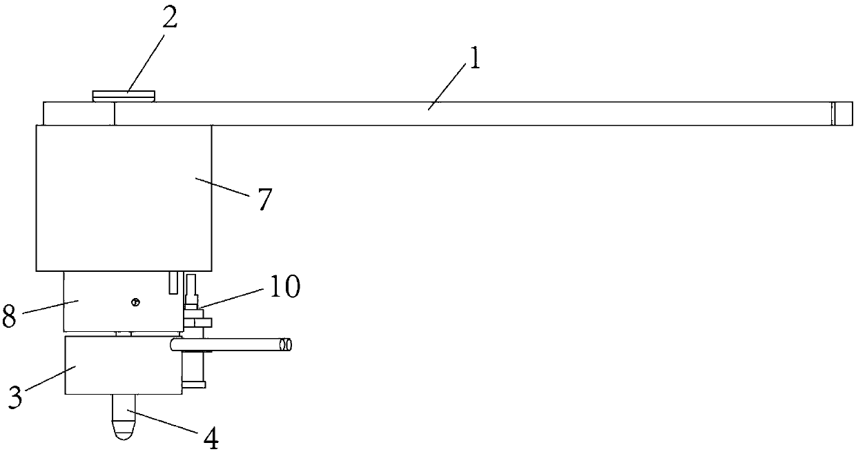
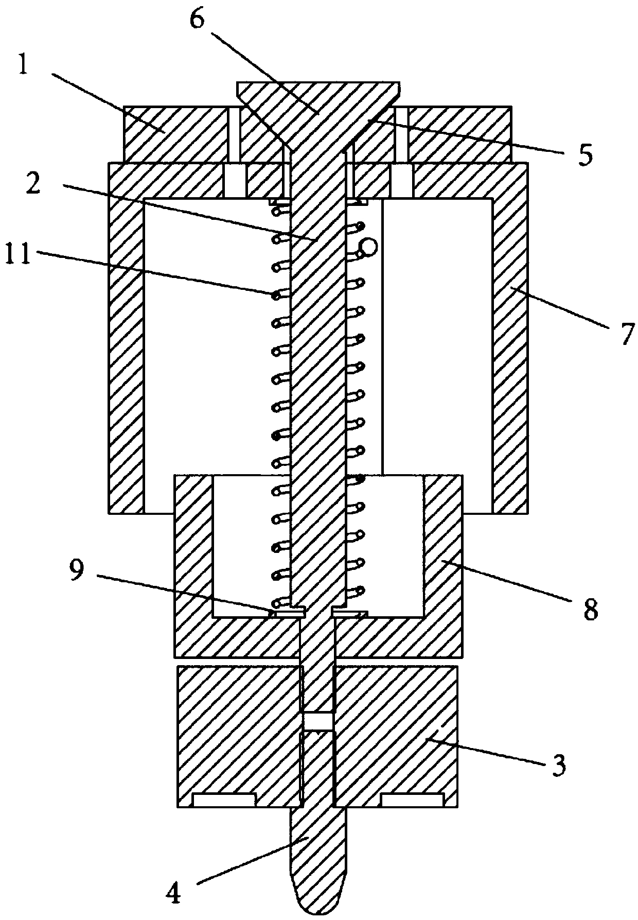
[0015] refer to figure 1 and figure 2 As shown, an embodiment of the rotor magnet conveying manipulator of the present invention includes a manipulator 1, one end of the manipulator is connected to a rotating lifting mechanism, and the rotating lifting mechanism can be composed of a cylinder and a rotating motor, which can assist the manipulator to complete moving, grabbing, For the blanking action, the other end of the mechanical arm is provided with a perforation, and the grasping shaft 2 is provided in the perforation, the electromagnet 3 is provided at the bottom of the grabbing shaft, and the central shaft 4 is provided at the bottom of the electromagnet. The downward moveme...


PUM


Abstract

The invention discloses a rotor magnet transport mechanical hand which includes a mechanical arm. One end of the mechanical arm is connected with a rotating lifting mechanism, the other end of the mechanical arm is provided with a punched hole, and a grabbing shaft is arranged in the punched hole. An electromagnet is arranged at the bottom of the grabbing shaft, a central shaft is arranged at thebottom of the electromagnet, a tapered groove with an opening facing upwards is formed in the punched hole, and a conical limiting bump is arranged at one end of the grabbing shaft. The conical limiting bump is arranged in the tapered groove and matched with the tapered groove for returning, and the surface of the grabbing shaft located between the mechanical arm and the electromagnet is further sleeved with a return spring. The rotor magnet transport mechanical hand is low in preparation cost and high in transport precision and has a protection return function.

Description

technical field [0001] The invention relates to a rotor magnet conveying manipulator. Background technique [0002] The rotor is generally composed of a magnet part and a rotating shaft part. When the rotor is prepared, the rotating shaft needs to be pressed into the magnet. Nowadays, many preparations are still in a semi-automatic production mode, that is, manual feeding and pressing into tooling preparation, and some automatic production However, due to the high accuracy of magnet delivery and feeding, the problem of position shift or crushing of magnets is prone to occur during production. Of course, there are some reliable production equipment, but the high cost of equipment is not conducive to use. Contents of the invention [0003] The technical problem to be solved by the present invention is to provide a rotor magnet conveying manipulator, which has low manufacturing cost, high conveying precision, and has protection and reset functions. [0004] In order to solve...

Claims


Application Information

Patent Timeline
IPC IPC(8): B23P19/02B25J9/00B25J15/06B25J19/00
CPCB23P19/007B23P19/02B25J9/0009B25J15/0608B25J19/0083
Inventor 易彬杨雷黄毅
Owner SUZHOU SUNMICRO AUTOMATION TECH CO LTD
Why Eureka
Try Eureka