Automatic monitoring method for high-speed milling cutter abrasion

A technology for tool wear and automatic monitoring, which is used in manufacturing tools, measuring/indicating equipment, metal processing machinery parts, etc. problems, to achieve the effect of predicting tool life, facilitating tool compensation and calibration, and avoiding damage

Active Publication Date: 2018-02-23
HEFEI INSTITUTES OF PHYSICAL SCIENCE - CHINESE ACAD OF SCI
View PDF5 Cites 22 Cited by
  • Summary
  • Abstract
  • Description
  • Claims
  • Application Information

AI Technical Summary

Problems solved by technology

The problem is that due to the irregular geometry and small size of the micromilling cutter, it is inconvenient to measure the amount of flank wear
In fact, there is currently no generally accepted method to perform subsequent machining compensation calibration according to the amount of wear reported.

Method used


Image

  • Automatic monitoring method for high-speed milling cutter abrasion
  • Automatic monitoring method for high-speed milling cutter abrasion
  • Automatic monitoring method for high-speed milling cutter abrasion

Examples


Embodiment Construction

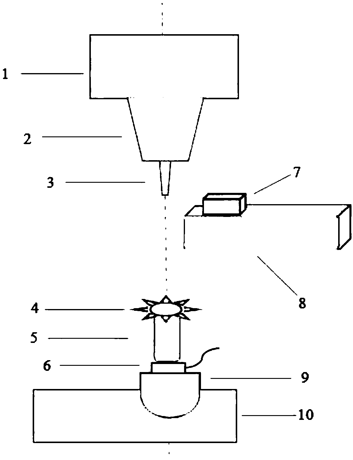
[0018] Depend on Figure 1-Figure 6 An automatic monitoring method for high-speed milling tool wear is shown. The imaging device faces the end of the working end of the tool 3 during the processing interval and collects images multiple times, and obtains multiple images. The processing interval is set by the program, which means In the processing program, multiple intervals are artificially added to take pictures; the tool 3 is a milling cutter of a CNC milling machine, preferably a micro-milling cutter, and the gray mean square error is performed on the central area of ​​each image collected in real time in the processing gap. Statistically, the central region includes the area where the cutter is located, and the image with the largest mean square error is selected as the target image, and the central region of each image is preferably the central region; the target image is the image of the front projection of the cutter 3 ends, and there are For the white area formed by we...


PUM


Abstract

The invention discloses an automatic monitoring method for high-speed milling cutter abrasion, and belongs to the field of precision manufacturing. The method comprises the steps that an imaging device directly faces the end of a cutter to collect images repeatedly within the machining intervals set by a numerical control program, wherein the cutter is a milling cutter of a numerical control milling machine; gray-level mean square error counting is carried out on the middle area ( including the area where the cutter is located) of each acquired image, the image with the maximum mean square error is selected as a focused target image, and a white area formed by abrasion exists in the target image; and the abrasion parameter characteristics of the white area are extracted, wherein the abrasion parameters comprise a length, a width and an area, and the abrasion parameter characteristics are used as representation forms of cutter abrasion. According to the automatic monitoring method for the high-speed milling cutter abrasion, the abrasion amount of a micro-milling cutter can be monitored, and the service life of the cutter can be predicted; and damage to a to-be-machined semi-finishedworkpiece or reduction of machining precision caused by the over-damaged cutter can be avoided.

Description

technical field [0001] The invention belongs to the field of precision manufacturing, in particular to an automatic monitoring method for high-speed milling tool wear. Background technique [0002] Micro tool wear status monitoring is a difficult and extremely critical problem in precision machining. Especially for high-speed micro-milling of small-scale blade parts made of difficult-to-machine materials such as titanium alloys, the micro-tool wears quickly and needs to be detected and replaced in time. Due to the small size of the tool, it is very difficult to actually measure the tool wear, which greatly affects the machining progress. Although some indirect measurement and monitoring methods have been proposed in the literature, focusing on current, cutting force, vibration, acoustic emission, temperature, workpiece surface texture, etc., these methods need to be further improved, especially for micro-milling, similar indirect measurement methods are affected by noise. ...

Claims


Application Information

Patent Timeline
Patent Type & Authority Applications(China)
IPC IPC(8): B23Q17/09
CPCB23Q17/0904B23Q17/0995
Inventor 朱锟鹏戴宜全余小龙施云高
Owner HEFEI INSTITUTES OF PHYSICAL SCIENCE - CHINESE ACAD OF SCI
Why Eureka
Try Eureka