Eureka AIR delivers breakthrough ideas for toughest innovation challenges, trusted by R&D personnel around the world.

Hydraulic lifting table for factory

A hydraulic lifting and factory technology, which is applied in the direction of lifting frames, lifting devices, lifting equipment safety devices, etc., can solve the problems of wasting manpower, heavy weight, and reducing work efficiency, etc., and achieve the effect of safe and reliable devices and protection of safety

Inactive Publication Date: 2018-02-23
WUXI AOTU AUTOMATION TECH CO LTD
View PDF0 Cites 0 Cited by
  • Summary
  • Abstract
  • Description
  • Claims
  • Application Information

AI Technical Summary

Problems solved by technology

[0002] In the power department, municipal department, post and telecommunications system, high-altitude installation of factories, mines, enterprises and institutions, the hydraulic lifting platform required for maintenance operations mainly includes the base, hydraulic power unit, etc. connected to each other to form a lifting mechanism. It is more convenient, but because the lifting operation must be connected to an external power supply, especially in places without external power supply, the hydraulic lifting platform cannot be used. For this reason, a special battery can be configured to provide a hydraulic power source, which has solved the problem that the hydraulic lifting platform cannot be used. , but the capacity of the storage battery is very limited. Not only does it need to be charged frequently, but also when the maintenance operation time is long, the capacity of the storage battery cannot meet the requirements of use, and the work reliability is not high. Furthermore, although the conventional hydraulic lifting platform has driving wheels , but because the driving wheel is not driven by power, its own weight is heavy, and in addition to the unevenness of the road surface in various environments, it reduces work efficiency and wastes manpower to push. There are many deficiencies in the design, so that it brings a lot of inconvenience to users who use this type of hydraulic lifting platform

Method used


Image

  • Hydraulic lifting table for factory
  • Hydraulic lifting table for factory
  • Hydraulic lifting table for factory

Examples


Embodiment Construction

[0015] The following will clearly and completely describe the technical solutions in the embodiments of the present invention with reference to the accompanying drawings in the embodiments of the present invention. Obviously, the described embodiments are only some, not all, embodiments of the present invention. Based on the embodiments of the present invention, all other embodiments obtained by persons of ordinary skill in the art without making creative efforts belong to the protection scope of the present invention.

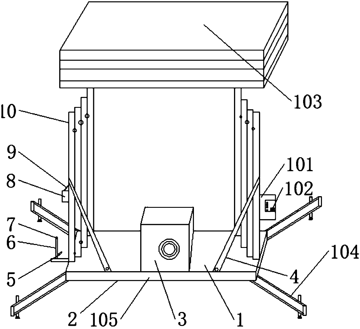
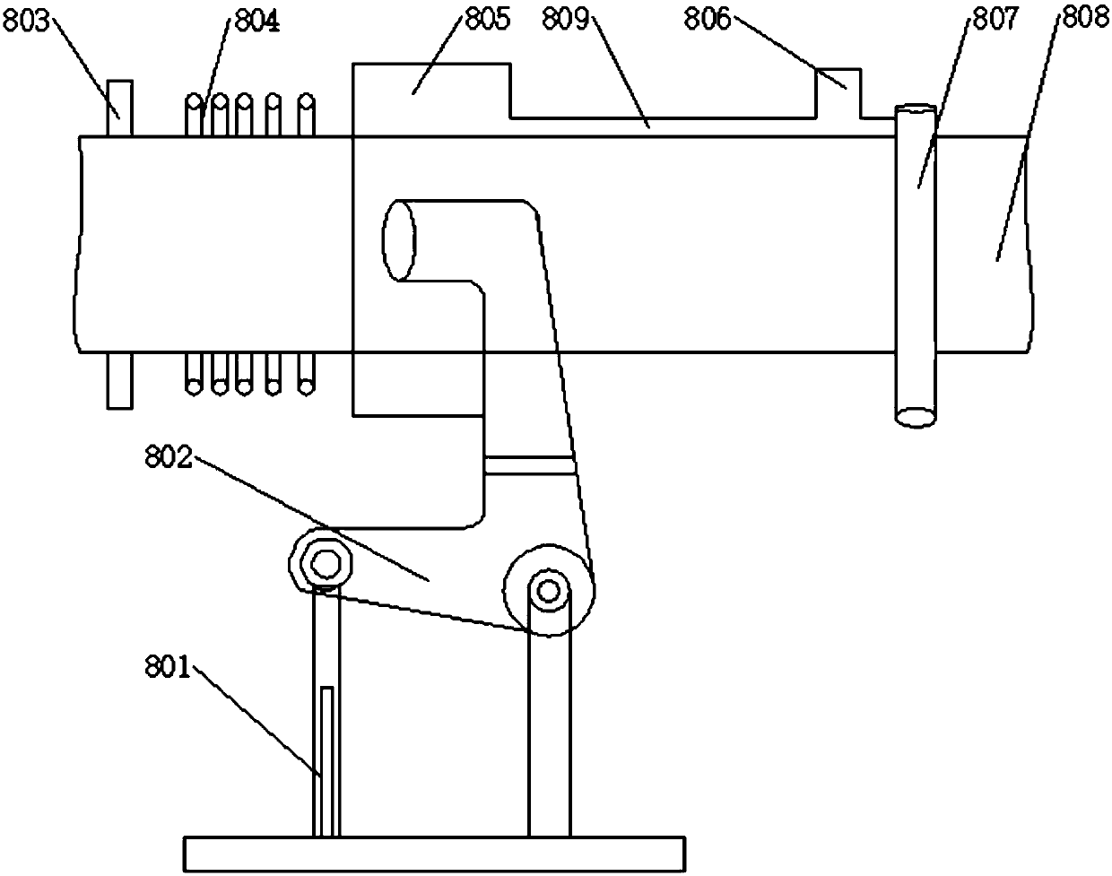
[0016] see Figure 1-2 , the present invention provides a technical solution: a hydraulic lifting platform used in factories, including a device main body 1 and several lifting cylinders 4, the device main body 1 is provided with a base 2, and the base 2 is surrounded by supports frame 104, the inside of the base 2 is provided with a leakage monitoring relay 105, the left side of the chain transmission device 10 is fixedly connected with a control box 8 and a ...


PUM


Abstract

The invention discloses a hydraulic lifting platform used in factories, which includes a main body of the device and several lifting cylinders, a base is arranged on the main body of the device, an electric leakage monitoring relay is arranged inside the base, a support frame is connected around the base, and a chain transmission device left There are control boxes and brake handles for side fixed connections, and a clutch handle is installed at the bottom left of the chain transmission device. Fixed connection, through the lifting column, the workers can carry out high-altitude operations at a certain height, so that the work efficiency is improved. There is a leakage monitoring relay. Monitoring, in case of an emergency, the leakage monitoring relay can cut off the power supply independently to protect the safety of people and equipment.

Description

technical field [0001] The invention relates to the field of high-altitude lifting technology, in particular to a hydraulic lifting platform used in factories. Background technique [0002] In the power department, municipal department, post and telecommunications system, high-altitude installation of factories, mines, enterprises and institutions, the hydraulic lifting platform required for maintenance operations mainly includes the base, hydraulic power unit, etc. connected to each other to form a lifting mechanism. It is more convenient, but because the lifting operation must be connected to an external power supply, especially in places without external power supply, the hydraulic lifting platform cannot be used. For this reason, a special battery can be configured to provide a hydraulic power source, which has solved the problem that the hydraulic lifting platform cannot be used. , but the capacity of the storage battery is very limited. Not only does it need to be char...

Claims


Application Information

Patent Timeline
Patent Type & Authority Applications(China)
IPC IPC(8): B66F11/04B66F7/02B66F7/28B66F17/00
CPCB66F11/04B66F7/02B66F7/28B66F17/006
Inventor 王宏
Owner WUXI AOTU AUTOMATION TECH CO LTD
Why Eureka
Eureka Blog
Learn More