Steel bar connection component for construction of high-rise building bearing piles

A technology for connecting components and buildings. It is applied in the direction of building components, building reinforcements, building structures, etc. It can solve the problems that the strength cannot meet the requirements of building construction and detachment, so as to ensure clamping strength, simple operation, and improve connection stability. sexual effect

Active Publication Date: 2018-02-23
西安建工绿色建筑集团有限公司
View PDF7 Cites 4 Cited by
  • Summary
  • Abstract
  • Description
  • Claims
  • Application Information

AI Technical Summary

Problems solved by technology

[0003] According to the depth of the pile hole, the axial length of the general steel cage is the same as the depth of the pile hole. However, when pouring a pile hole with a relatively long depth, the construction personnel usually splice multiple steel cages of equal length, and then hoist them to In the pile hole, concrete is poured at the end to shorten the construction time; when the existing connecting piece is hoisted in the steel cage, the two steel cages after splicing are prone to detachment at the joint, which leads to lowering into the pile hole The reinforcement cages of the piles are separated from each other, which eventually leads to the fact that the strength of the pile holes after pouring cannot meet the construction requirements

Method used


Image

  • Steel bar connection component for construction of high-rise building bearing piles
  • Steel bar connection component for construction of high-rise building bearing piles
  • Steel bar connection component for construction of high-rise building bearing piles

Examples


Embodiment 1

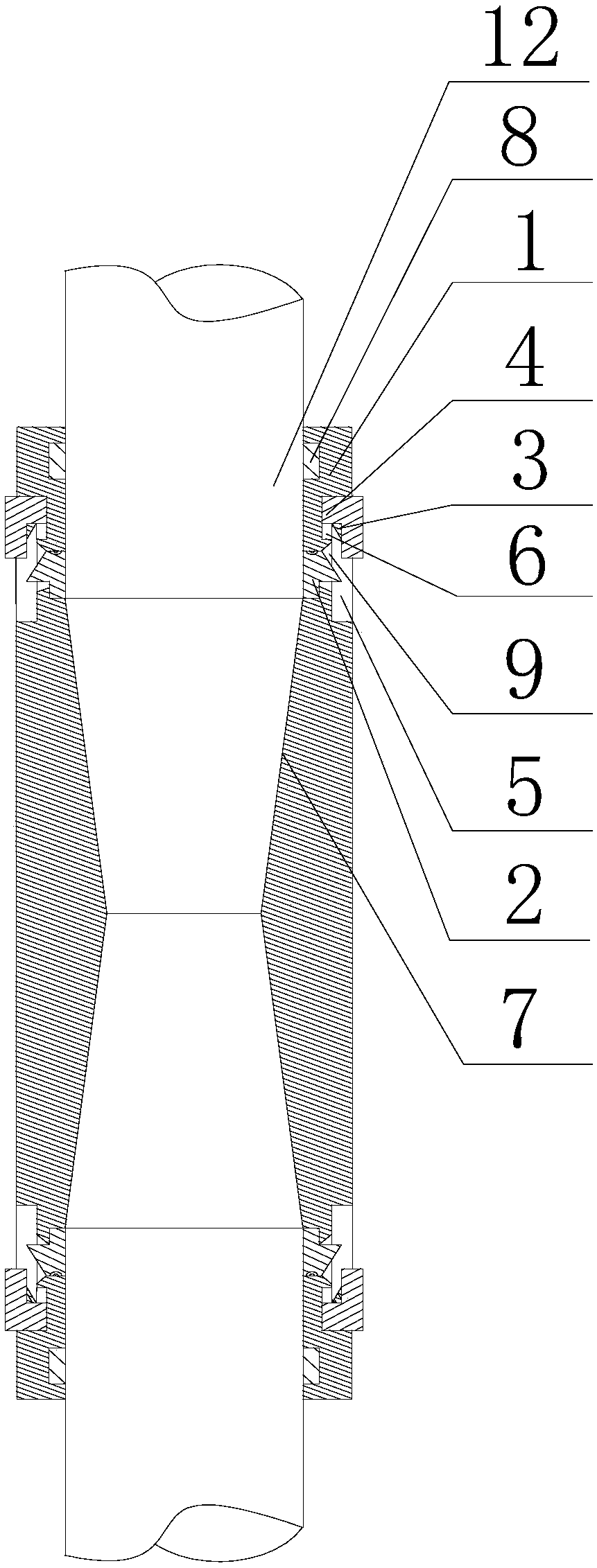
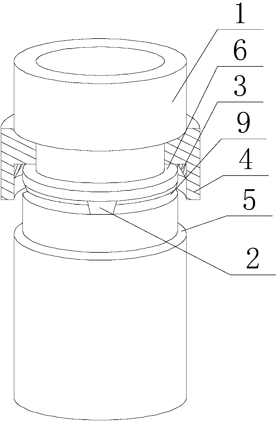
[0027] Such as Figure 1~3As shown, this embodiment includes a connecting cylinder 1 and a snap ring 7 fixed on the outer peripheral wall of one end of the connecting cylinder 1. A nut 8 threadedly fitted with the connecting cylinder 1 is provided on the connecting cylinder 1, and the nut 8 and the snap ring 7 Located on the same side of the connecting cylinder 1, a chute 6 is provided on the outer peripheral wall of the other end along the circumferential direction of the connecting cylinder 1, and a chute 6 is opened on the outer peripheral wall of the connecting cylinder 1 along the circumferential direction. Connected limit groove 5, and an annular groove 9 is provided at the bottom of the groove along the circumferential direction of the chute 6, at least one through hole communicating with the inside of the connecting cylinder 1 is opened on the annular groove 9, and the pressure block 2 is hinged by a torsion spring. In the through hole, and the inner side wall of the p...

Embodiment 2

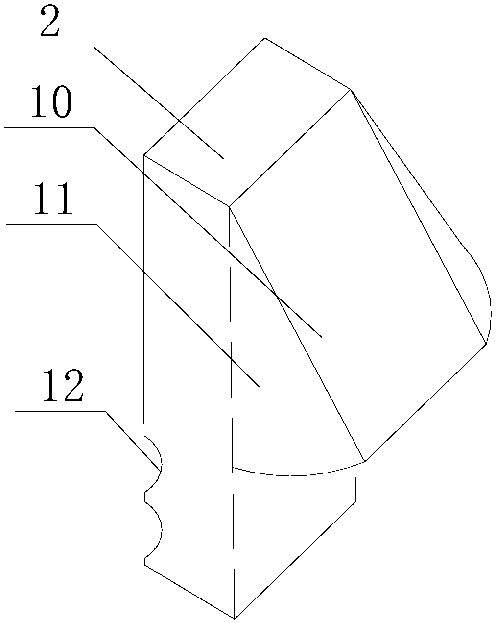
[0031] Such as Figure 1~3 As shown, the longitudinal section of the annular groove 9 in this embodiment is triangular. Since the outer wall of the pressure block 2 partially protrudes from the annular groove 9, and the cross-section of the protrusion is also triangular, so that the protrusion 3 moves to contact with the outer wall of the contact block 10 and squeezes it, and the protrusion is compressed. The hinge point rotates, so that the protrusion moves into the annular groove 9, and the rotation of the snap ring is stopped. At this time, the annular protrusion 3 continues to squeeze the pressure block 2, and the inner side wall of the pressure block 2 continues to hold the main rib 12. Hold, because the inner diameter of the protrusion 3 is in an increasing state, that is, the longitudinal section of the partial section of the protrusion 3 is triangular, and the contact block 10 matched with the protrusion 3 rotates at a relatively large angle in the annular groove 9 who...


PUM


Abstract

The invention discloses a steel bar connection component for construction of high-rise building bearing piles. The steel bar connection component comprises a connection cylinder and a snap ring. A nutis arranged on the connection cylinder. A sliding groove and a limiting groove communicated with the sliding groove are formed in the outer circumferential wall of the connection cylinder. An annulargroove is formed in the bottom of the sliding groove. A through hole is formed in the annular groove. The inner side wall of a press block is flush with the inner circumferential wall of the connection cylinder. The outer side wall of the press block is protruded on the outer end wall of the through hole and disposed in the annular groove. Threads are arranged at the bottom of the sliding groove.A press ring is arranged in the sliding groove in a sleeved mode. A protrusion is arranged on the inner circumferential wall of the press ring. The inner diameter of the protrusion increases gradually from one end, where the press ring is located, to the direction close to the connection cylinder along the axis of the connection cylinder. A contact block is arranged on the outer side wall of thepress block. One end of the connection cylinder is fixed to a rotating disc, and the other end of the connection cylinder clamps and fastens a main rib, so that the main rib is prevented from overturning in the connection cylinder to influence the welding effect between the main rib and transverse ribs, and the strength of a reinforcement cage is guaranteed.

Description

technical field [0001] The invention relates to the field of building construction, in particular to a steel bar connection assembly for high-rise building bearing pile construction. Background technique [0002] A deep foundation consisting of a pile and a pile cap connected to the top of the pile (referred to as a cap) or a single pile foundation connected by a column and a pile foundation, referred to as a pile foundation. When the pile body is completely buried in the soil and the bottom of the cap is in contact with the soil, it is called a low cap pile foundation; when the upper part of the pile body is exposed to the ground and the bottom of the cap is above the ground, it is called a high cap pile foundation; and construction piles The foundation is usually a low cap pile foundation. In the construction of bridges and culverts or high-rise buildings, low cap piles will be used. The construction process is to use machine punching and water mill drilling, and the hole...

Claims


Application Information

Patent Timeline
Patent Type & Authority Applications(China)
IPC IPC(8): E04C5/16
CPCE04C5/165
Inventor 杨蒙蒙
Owner 西安建工绿色建筑集团有限公司
Why Eureka
Try Eureka