Concrete vibrator

A vibrator, concrete technology, applied in the direction of construction, building structure, building materials, etc., can solve the problems of motor and concrete contaminating the motor, affecting the quality and effect of vibration, affecting the ventilation and heat dissipation of the motor, and achieving improved expectations Economic effect, shortening the time to recover investment, and convenient operation

Inactive Publication Date: 2018-02-23
王中荣
View PDF4 Cites 0 Cited by
  • Summary
  • Abstract
  • Description
  • Claims
  • Application Information

AI Technical Summary

Problems solved by technology

[0010] One: The existing concrete vibrator uses a chassis-type supporting motor. During use, the motor is easily in contact with the concrete and contaminates the motor, which will inevitably affect the ventilation and heat dissipation of the motor.
[0011] Second: The connection and sealing of the corresponding casing of the existing concrete vibrator is not firm, and the overall performance is poor. Its center of gravity is unstable and may roll over during use on the construction site, which seriously affects the vibration quality and effect.
[0012] Third; for the existing concrete vibrator, along with the vibration, the auxiliary units such as cable assemblies and switch assemblies are easily damaged or malfunction due to vibration
[0013] Fourth: According to market research, it is found that the concrete vibrator used in the market has a complex structure, is expensive, and has high production costs, which will directly affect the economic benefits of use.

Method used


Image

  • Concrete vibrator
  • Concrete vibrator
  • Concrete vibrator

Examples


Embodiment Construction

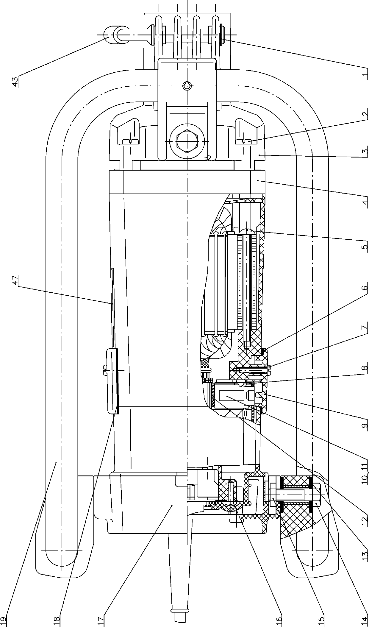
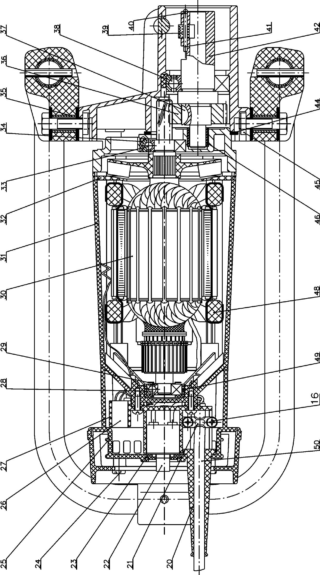
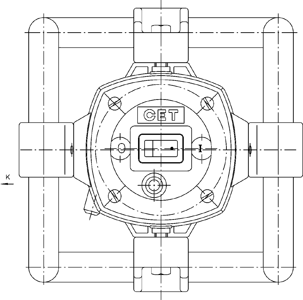
[0048] The following will be combined with Figure 1-Figure 4 The present invention is described in detail, and the technical solutions in the embodiments of the present invention are clearly and completely described. Apparently, the described embodiments are only some of the embodiments of the present invention, not all of them. Based on the embodiments of the present invention, all other embodiments obtained by persons of ordinary skill in the art without making creative efforts belong to the protection scope of the present invention.

[0049] The present invention provides a kind of single-phase concrete vibrator here through improvement, as Figure 1-Figure 4 As shown, the present invention can be implemented in the following manner; including a reduction box 3, a middle cover 4, a cover plate 9, a rear end cover 17, a support frame assembly 19, a tail cover 25, an armature assembly 30, a casing 31, a first-stage Driven gear 36, main shaft 42, stator assembly 48, cable asse...


PUM


Abstract

The invention discloses a concrete vibrator. The shell part of the concrete vibrator is composed of a middle cover, a cover plate, a rear end cover, a tail cover and a casing; a reduction box is located at the end of the casing; assembly, primary driven gear, main shaft and stator assembly; one end of the cable assembly protrudes from the casing; an arc-shaped support frame assembly is fixedly installed on the outside of the casing; the upper end of the support frame assembly and the reduction box is passed through bolts, square nuts and The support sleeve is connected; the reduction box and the middle cover are connected and fixed by screw A, and the contact surface is sealed by a sealing ring. The motor of this product is fixed by the steel pipe frame suspension support, which solves the problem that the chassis-supported motor may roll over during use on the construction site. The motor is easy to contact with the concrete and contaminate the motor, which affects the ventilation and heat dissipation of the motor. At the same time, general-purpose parts are used in the design. , thereby reducing product manufacturing costs and shortening the time to recover investment.

Description

technical field [0001] The invention relates to a concrete vibration device, in particular to a single-phase concrete vibrator. Background technique [0002] According to the statistics of "China's Power Tool Industry Production and Sales Demand Forecast and Transformation and Upgrading Analysis Report", power tools are mainly divided into metal cutting power tools, grinding power tools, assembly power tools and railway power tools. [0003] Common electric tools include electric drills, electric grinders, electric wrenches and electric screwdrivers, electric hammers and impact drills, concrete vibrators, and electric planers. However, a concrete vibrator is an electric tool that compacts poured concrete by vibrating. [0004] With the recovery and prosperity of the real estate industry and the construction industry, the market demand for concrete vibrators is increasing day by day. So far, there are many companies in the industry with an annual output of about 200,000 unit...

Claims


Application Information

Patent Timeline
Patent Type & Authority Applications(China)
IPC IPC(8): E04G21/06
CPCE04G21/06
Inventor 王中荣
Owner 王中荣
Why Eureka
Try Eureka