
Seismic trace integration imaging method and system

A technology for integrating images and seismic traces, applied in the field of seismic trace integration imaging methods and systems, to achieve the effect of improving accuracy

Active Publication Date: 2019-02-19
CHINA PETROLEUM & CHEM CORP +1
View PDF7 Cites 0 Cited by
  • Summary
  • Abstract
  • Description
  • Claims
  • Application Information

AI Technical Summary

Problems solved by technology

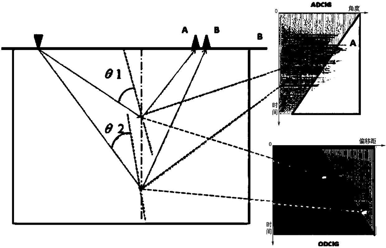
[0003] Like other prestack migration methods, common shot prestack migration can also output common imaging gathers to obtain offset domain common imaging point gathers (ODCIG, Offset Domain Common Image Gather), but in the case of strong lateral velocity variation , there are kinematic and dynamic artifacts in the common imaging point gather in the offset domain

Method used


Image

  • Seismic trace integration imaging method and system
  • Seismic trace integration imaging method and system
  • Seismic trace integration imaging method and system

Examples


Embodiment approach 1

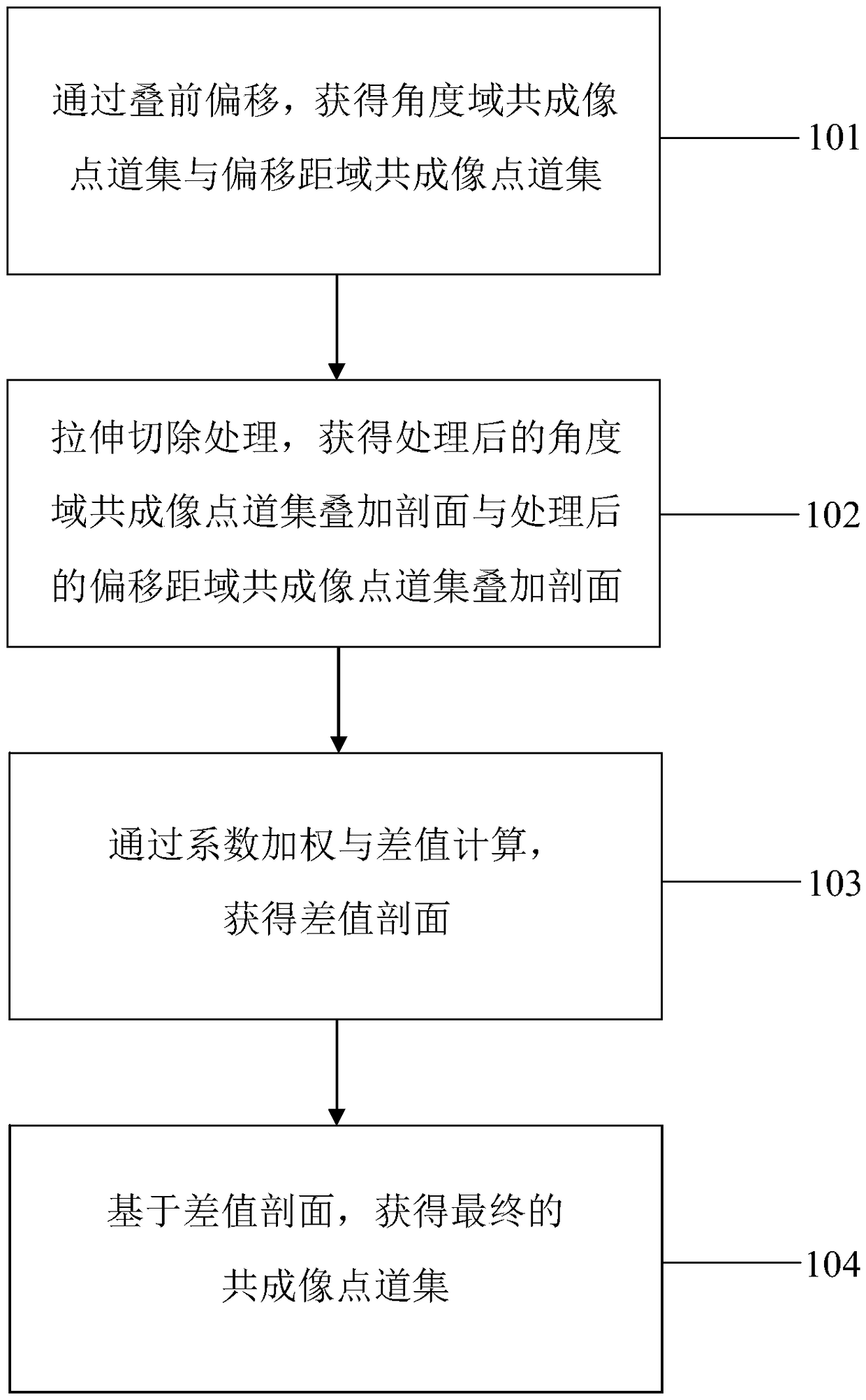
[0019] figure 1 A flowchart showing the steps of the seismic trace integration imaging method according to the present invention.

[0020] In this embodiment, the seismic trace imaging method according to the present invention includes: step 101, based on the common center point gather and the seismic velocity field, through prestack migration, obtain the angle domain common imaging point gather and the offset domain Common imaging point gather; step 102, based on the common imaging point gather in the angle domain and the common imaging point gather in the offset domain, through stretching and resection processing, the processed angle domain common imaging point gather superposition section and processed The stacked profile of the common imaging point gather in the offset domain; Step 103, based on the processed stacked profile of the common imaging point gather in the angle domain and the processed stacked profile of the common imaging point gather in the offset domain, by c...

Embodiment approach 2

[0058] According to an embodiment of the present invention, a seismic trace integration imaging system is provided, and the system may include: based on the common center point gather and the seismic velocity field, through prestack migration, obtain the common imaging point gather in the angle domain The unit of the common imaging point gather with the offset domain; it is used to obtain the processed angle domain common imaging point gather through stretching and cutting processing based on the common imaging point gather of the angle domain and the common imaging point gather of the offset domain A unit for stacking profiles and processed offset-domain common-imaging point gather stacking profiles; used to stack profiles based on processed angle-domain common-imaging point gathers and processed offset-domain common-imaging point gathers Profile, through coefficient weighting and difference calculation, to obtain the unit of the difference profile; and the unit used to weight...


PUM


Abstract

The invention discloses a seismic gather imaging method and system. The method comprises the following steps: based on a common midpoint gather and a seismic velocity field, through pre-stack migration, obtaining an angle domain common image gather and an offset domain common image gather; based on the angle domain common image gather and the offset domain common image gather, through stretching cutting processing, obtaining a stacked section of the angle domain common image gather after processing and a stacked section of the offset domain common image gather after processing; based on the stacked section of the angle domain common image gather after processing and the stacked section of the offset domain common image gather after processing, obtaining a difference section through coefficient weighting and difference calculating; and based on weighting combination and difference section calculation of the stacked section of the angle domain common image gather after processing and thestacked section of the offset domain common image gather after processing, obtaining a final common image point gather.

Description

technical field [0001] The present invention relates to the technical field of oil and gas geophysics, and more specifically, relates to a seismic trace integration imaging method and system using difference profiles. Background technique [0002] Seismic imaging is a key technology of seismic exploration, whether in the research field or in industrial applications, it is a hot issue in the history of reflection seismic methods. Generally speaking, in addition to outputting imaging results, prestack migration can also output partial imaging data that is not fully superimposed. The common image gather (CIG, Common Image Gather) is formed by combining the traces with the same lateral position of the imaging points in all partial imaging data. It has three uses: first, migration velocity analysis based on common imaging gathers; second, amplitude versus offset variation (AVO, Amplitude Versus Offset) on common imaging gathers with high amplitude fidelity Or the analysis of am...

Claims


Application Information

Patent Timeline
Patent Type & Authority Patents(China)
IPC IPC(8): G01V1/28
CPCG01V1/28
Inventor 刘志远刘喜武霍志周刘宇巍张远银
Owner CHINA PETROLEUM & CHEM CORP
Learn More