
Curved surface display panel correction method and system,

A technology of curved surface display and correction method, which is applied in the field of correction method and system of curved surface display panel, to achieve the effect of improving product quality

Inactive Publication Date: 2018-02-23
HKC CORP LTD +1
View PDF4 Cites 13 Cited by
  • Summary
  • Abstract
  • Description
  • Claims
  • Application Information

AI Technical Summary

Problems solved by technology

At present, curved LCD TVs are becoming more and more popular among the public, but after the panel is bent from a flat state to a curved state, the liquid crystal in it will be squeezed by the bending stress of the glass and other unpredictable image defects Mura ( It does not exist in the flat state of the panel, but it is added after bending), so the defect mura cannot be repaired in the flat state of the panel, and then the panel is bent into a curved surface. The only way is to repair the defect mura compensation in the state of the curved panel
[0005] The image defect mura compensation and repair methods in the industry are all based on the panel being in a flat state, because there is a difference in the display area of ​​the panel captured by the camera in the flat state and the curved state, and the flat length in the curved state is smaller than that in the flat state, so It is not possible to directly use the existing planar image defect mura compensation repair method to calculate the defect mura compensation value of each area of ​​the panel in the curved surface state, and it is necessary to develop an image defect mura phenomenon compensation method suitable for the curved surface panel

Method used


Image

  • Curved surface display panel correction method and system,
  • Curved surface display panel correction method and system,
  • Curved surface display panel correction method and system,

Examples


Embodiment Construction

[0026] In order to further explain the method for calibrating a curved display panel of the present invention and the technical means adopted by the system to achieve the intended purpose of the invention and the effects achieved, the following is combined with the accompanying drawings and preferred embodiments to discuss the proposed method according to the present invention. The specific implementation, structure, features and effects of the calibration method of the curved display panel and its system are described in detail.

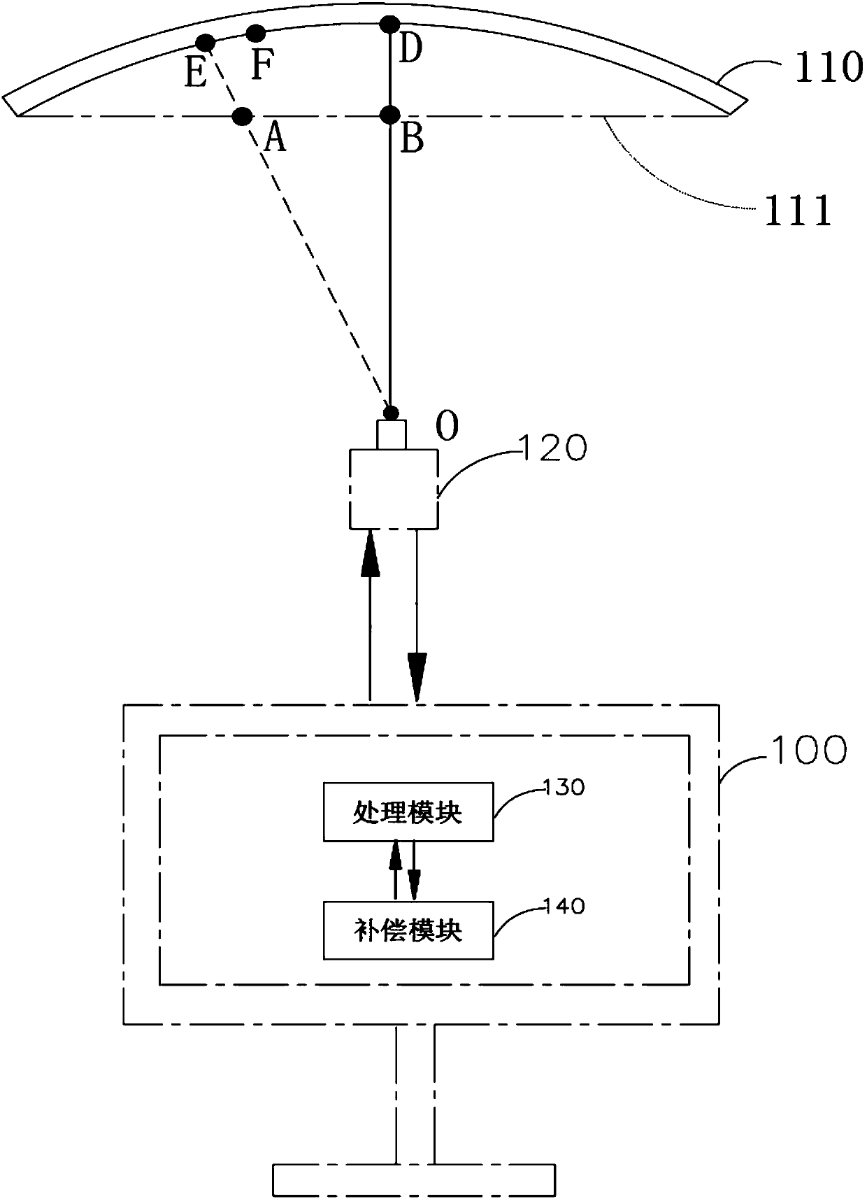
[0027] Please refer to figure 1 , Which is a schematic structural diagram of an exemplary calibration system of a curved display panel.

[0028] in figure 1 Among them, an exemplary correction system for a curved display panel includes: a computer device 100; a curved display panel 110, assuming that there is a Mura (image defect phenomenon) at point E on the curved display panel 110, the curved display panel displays pure grayscale images The phenomenon...


PUM


Abstract

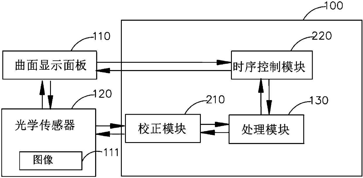
The invention discloses a curved surface display panel correction method and system. The curved surface display panel correction method comprises steps of providing a curved surface display panel andan optical sensor, photographing the curved surface display panel through the optical sensor, obtaining position information of an image default compensation point of the curved surface display panelaccording to a collected image, obtaining corrected position information of the image default compensation point, calculating an image default position compensation value of the curved surface displaypanel through a processing module according to the obtained position information of the image default compensation point, storing the image default position compensation value into a time sequence control module and assembling the time sequence control module with the curved surface display panel. As a result, the curved surface display panel correction method and system can correctly find the position of the compensation point in the curved surface display panel, performs correct default compensation on the curved surface display panel under a curved surface state and improves quality of a product of the curved surface display panel.

Description

Technical field [0001] The present invention relates to the field of display technology, in particular to a correction method and system for a curved display panel. Background technique [0002] With the development of liquid crystal display (LCD) towards lighter, thinner and larger, due to some uncontrollable factors in the actual manufacturing process, the physical characteristics of the LCD display panel are different, resulting in more than one pixel. Within the range of, the phenomenon of uneven brightness when displaying pure grayscale images, which is called the Mura phenomenon of image defects in the industry. [0003] The image defect Mura phenomenon has become a bottleneck restricting the development of LCD. By improving the process level or improving the purity of the material, the probability of the occurrence of the image defect Mura phenomenon can be reduced. For the LCD display panel that has been manufactured, its physical characteristics have been finalized. In o...

Claims


Application Information

Patent Timeline
IPC IPC(8): G09G3/36
CPCG09G3/36G09G2320/10
Inventor 赵文勤
Owner HKC CORP LTD
Learn More