LED luminous light source

A light-emitting light source, LED chip technology, applied in electrical components, electrical solid devices, circuits, etc., can solve problems such as damage to LED chips, lack of heat dissipation capability, and inability to maintain, to improve heat dissipation performance, facilitate maintenance, and accelerate heat dissipation. Effect

Inactive Publication Date: 2018-02-23
夏烬楚
View PDF0 Cites 0 Cited by
  • Summary
  • Abstract
  • Description
  • Claims
  • Application Information

AI Technical Summary

Problems solved by technology

However, the circuit board mainly plays a conductive role, and basically has no limited heat dissipation capability. When the heat generated by the LED chip accumulates too much, it is easy to cause damage to the LED chip. Moreover, once the LED chip is damaged, it is basically impossible to repair it. Replace with a new LED light source

Method used


Image

  • LED luminous light source
  • LED luminous light source

Examples


Embodiment Construction

[0012] The following will clearly and completely describe the technical solutions in the embodiments of the present invention with reference to the accompanying drawings in the embodiments of the present invention. Obviously, the described embodiments are only some, not all, embodiments of the present invention. Based on the embodiments of the present invention, all other embodiments obtained by persons of ordinary skill in the art without making creative efforts belong to the protection scope of the present invention.

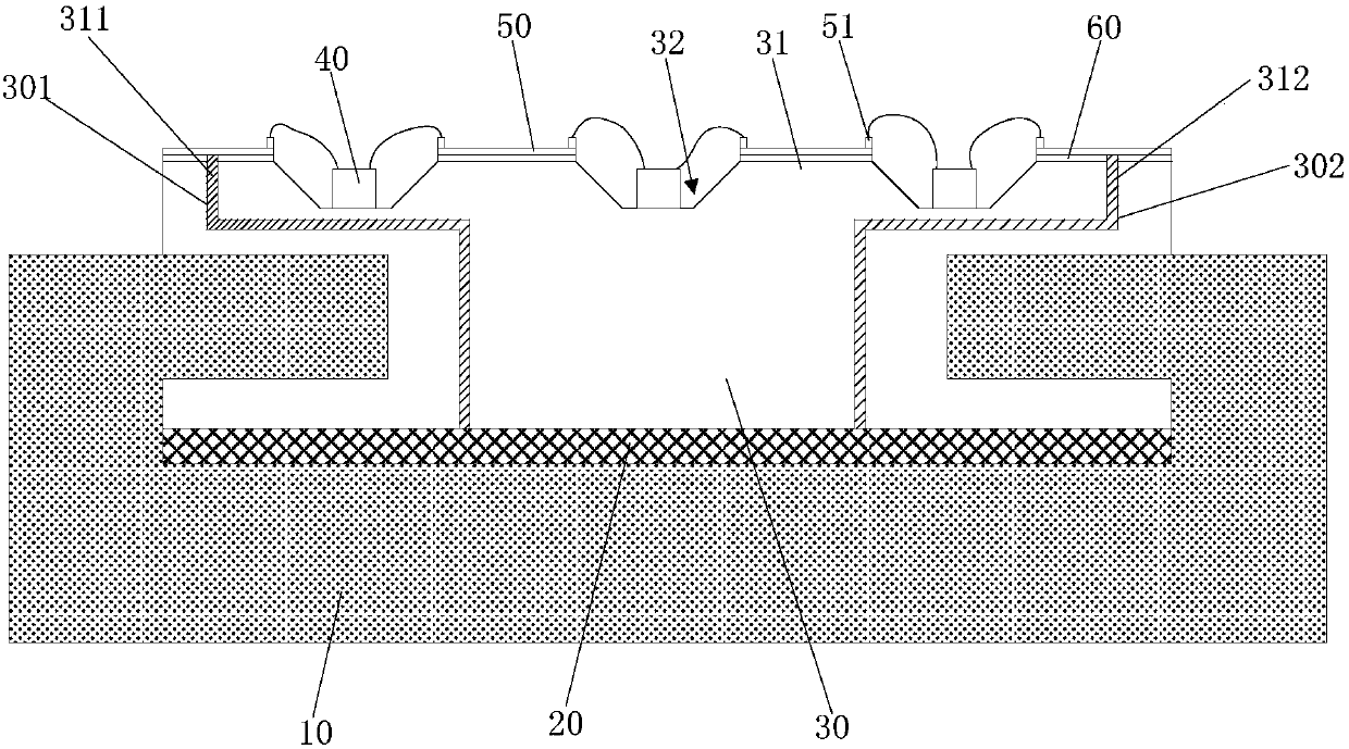
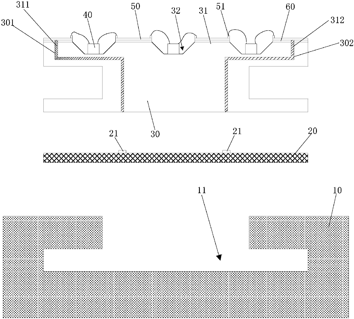
[0013] refer to figure 1 and figure 2 , the LED light source of the embodiment of the present invention includes a metal base 10 , a circuit board 20 and a ceramic base 30 . The metal base 10 is provided with a T-shaped slot 11 , the circuit board 20 is embedded in the bottom of the T-shaped slot 11 , and the ceramic substrate 30 is arranged in an I-shape.

[0014] A plurality of LED chips 40 and a plurality of metal thin film electrodes 50 are fixed on the...


PUM


Abstract

The invention discloses an LED light source. It includes a metal base, a circuit board and a ceramic base. The metal base is provided with a T-shaped slot. The circuit board is embedded in the bottom of the T-shaped slot. The ceramic base is set in an I-shape. The LED chip and the metal film electrode are connected at intervals. The upper surface of the ceramic substrate is provided with a plurality of outwardly protruding protrusions, and a groove is formed between two adjacent protrusions. The LED chip is arranged in the groove, and the metal film electrode is arranged On the protruding part, the ceramic substrate is provided with two through channels, and electrode wires are formed in the channels. The upper ends of the two electrode wires are respectively electrically connected to the leftmost and rightmost metal film electrodes. The ceramic substrate is embedded in the T-shaped In the groove, two parallel electrode contact strips are arranged on the circuit board, the ceramic substrate can be embedded in the T-shaped groove, and the lower ends of the two electrode wires are respectively electrically connected to the two electrode contact strips. The invention can improve heat dissipation performance and facilitate maintenance.

Description

technical field [0001] The invention relates to the technical field of semiconductors, in particular to an LED light source. Background technique [0002] With the continuous improvement of light efficiency of LEDs (Light Emitting Diodes, light emitting diodes), in the field of general lighting, there is a trend of using LEDs to replace traditional light emitting devices. However, the LED light source usually generates a lot of heat when it is working, and the heat needs to be dissipated in time, otherwise it will affect the normal operation and service life of the LED light source. [0003] The existing LED light source includes a circuit board and LED chips arranged on the circuit board. However, the circuit board mainly plays a conductive role, and basically has no limited heat dissipation capability. When the heat generated by the LED chip accumulates too much, it is easy to cause damage to the LED chip. Moreover, once the LED chip is damaged, it is basically impossible...

Claims


Application Information

Patent Timeline
IPC IPC(8): H01L25/13H01L33/62H01L33/64
CPCH01L25/13H01L33/62H01L33/642H01L33/647
Inventor 夏烬楚
Owner 夏烬楚
Why Eureka
Try Eureka