Switch-type coaxial connector

A coaxial connector, switch-type technology, applied in the direction of connection, two-part connection device, fixed/insulated contact member, etc., can solve the problems of increasing the overall width of the connector, increasing the height of the radio frequency head, and not adapting to the development of miniaturization. , to achieve the effect of miniaturization development, reducing the occupied space, and improving the phenomenon of tin climbing

Active Publication Date: 2018-02-23
LINKCONN ELECTRONICS
View PDF9 Cites 0 Cited by
  • Summary
  • Abstract
  • Description
  • Claims
  • Application Information

AI Technical Summary

Problems solved by technology

[0002] For the prior art related to the present invention, please refer to the Chinese Invention Patent No. CN104471802B announced on October 19, 2016, which discloses a coaxial connector It is a coaxial connector to which a coaxial connector for inspection is attached. The coaxial connector for inspection has a probe extending in the vertical direction and a cylindrical first outer conductor surrounding the probe. The coaxial connection The device includes: a main body having an upper surface and a bottom surface, and a hole for inserting the above-mentioned probe from the upper side to the lower side; a second outer conductor including a periphery surrounding the hole and inserted into the first outer conductor. A cylindrical part inside the conductor, an outer conductor body part provided on the above-mentioned upper surface, and an outer conductor fixing part clamping the above-mentioned body together with the outer conductor body part by being drawn out from the outer conductor body part to the above-mentioned bottom surface; a fixed terminal , which is fixed to the main body; and a movable terminal including a movable

Method used


Image

  • Switch-type coaxial connector
  • Switch-type coaxial connector
  • Switch-type coaxial connector

Examples


Embodiment Construction

[0026] The present invention will be further described below in conjunction with the accompanying drawings and embodiments.

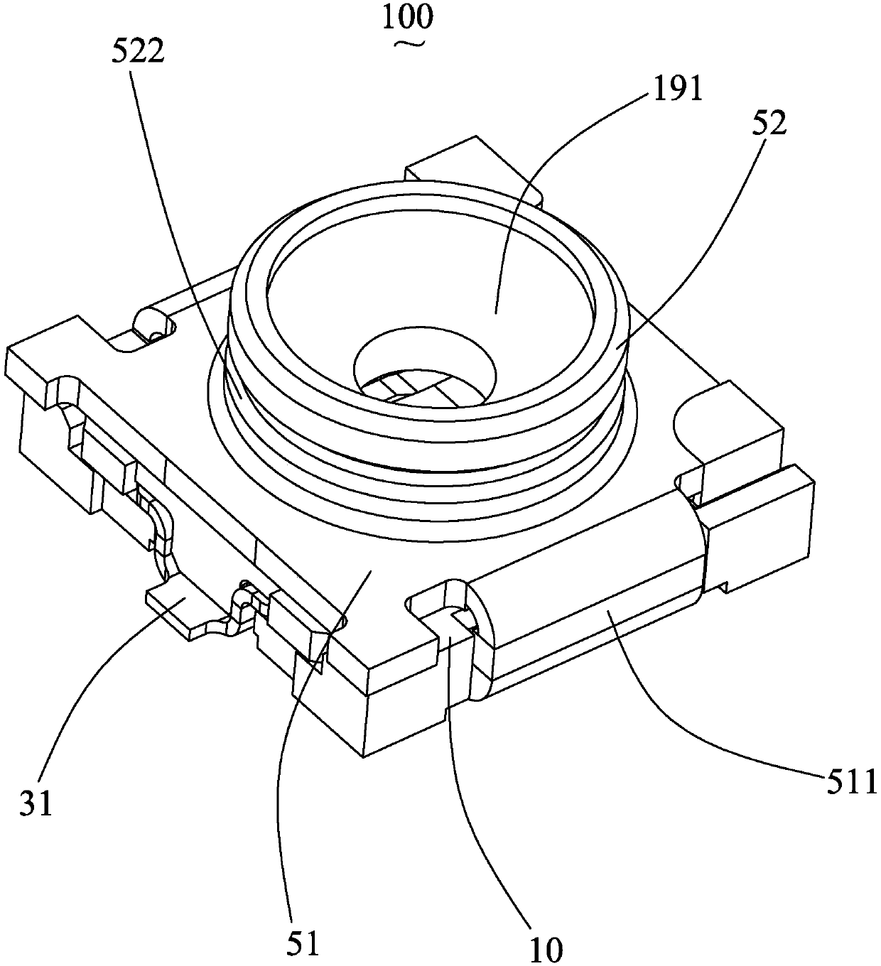
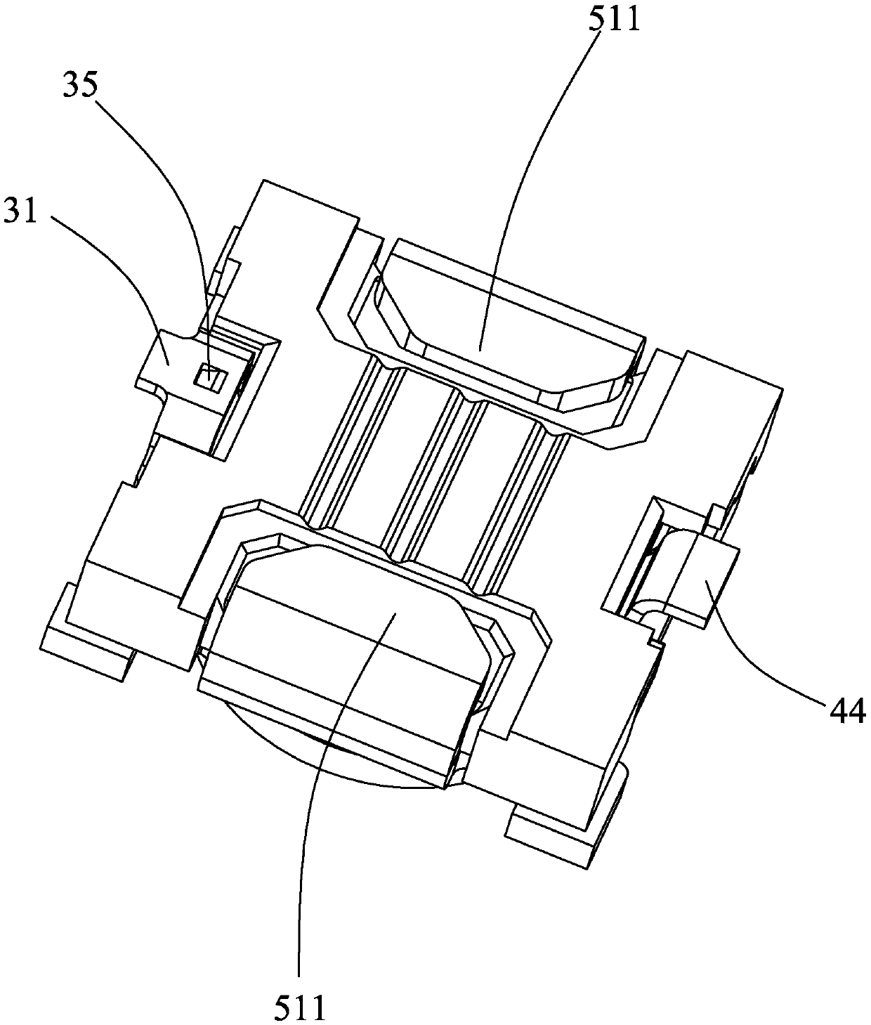
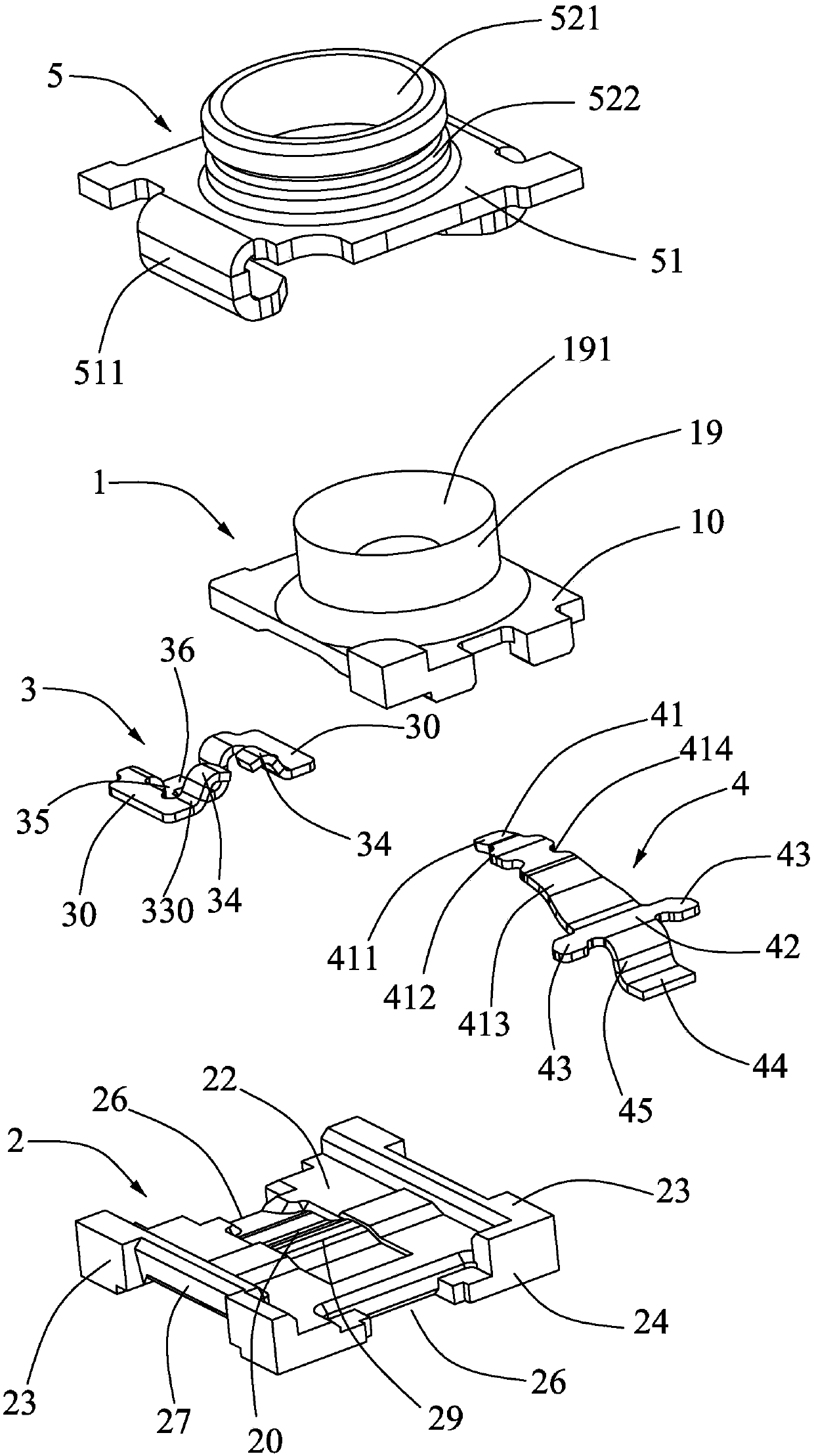
[0027] Such as Figure 1 to Figure 7 As shown, a switchable coaxial connector 100 includes an insulating body 1 , an insulating base 2 , fixed terminals 3 , movable terminals 4 and a metal shell 5 .

[0028] The fixed terminal 3 and the movable terminal 4 are clamped between the insulating base 2 and the insulating body 1 , and the metal shell 5 fixes the insulating base 1 and the insulating body 2 together. The insulative body 1 includes a bottom plate 10 and a columnar portion 19 extending upward from the bottom plate 10 . The columnar portion 19 is provided with a cylindrical hole 191 penetrating downward through the insulative body 1 for accommodating a central terminal of a mating connector. The bottom plate portion 10 has a first side 11 and a second side 12 oppositely disposed, the fixed terminal 3 is installed on the first side 11 of the insula...


PUM


Abstract

The invention discloses a switch-type coaxial connector. The switch-type coaxial connector comprises an insulation substrate, an insulation body, a fixed terminal, a movable terminal and a metal shell, wherein the fixed terminal and the movable terminal are clamped between the insulation substrate and the insulation body, the insulation substrate and the insulation body are fixed by the metal shell, the insulation body is provided with a first side and a second side which are opposite to each other, the fixed terminal is arranged at the first side of the insulation body, the movable terminal is arranged at the second side of the insulation body and is provided with a contact part, a gap is encircled by a first side arm, a second side arm and a third side arm of the fixed terminal, and a tail end of the movable terminal extends to a lower side of the gap. The fixed terminal forms a surrounding structure, the gap accommodated with the tail end of the movable terminal is formed, the occupancy space of the movable terminal on the connector is reduced, and miniaturization development of the switch-type coaxial connector is achieved.

Description

technical field [0001] The invention relates to a coaxial connector, in particular to a structure setting of a dynamic and static terminal of a switch type coaxial connector. Background technique [0002] For the prior art related to the present invention, please refer to the Chinese Invention Patent No. CN104471802B announced on October 19, 2016, which discloses a coaxial connector that is installed with a coaxial connector for inspection. The coaxial connector for inspection includes a probe extending in the vertical direction and a cylindrical first outer conductor surrounding the probe, and the coaxial connector includes: a main body having an upper surface and a bottom surface and forming There is a hole for the above-mentioned probe to be inserted from the upper side to the lower side; the second outer conductor includes a cylindrical portion that surrounds the hole and is inserted into the first outer conductor, and an outer conductor body provided on the upper surfac...

Claims


Application Information

Patent Timeline
IPC IPC(8): H01R13/40H01R24/40
CPCH01R13/40H01R24/40
Inventor 闻豪阮军
Owner LINKCONN ELECTRONICS
Why Eureka
Try Eureka