
Evaporative Fuel Treatment Unit

A technology for evaporating fuel and processing device, applied in the field of evaporating fuel processing device, can solve problems such as abnormal gas noise, and achieve the effect of suppressing abnormal noise

Active Publication Date: 2018-12-25
NISSAN MOTOR CO LTD
View PDF3 Cites 0 Cited by
  • Summary
  • Abstract
  • Description
  • Claims
  • Application Information

AI Technical Summary

Problems solved by technology

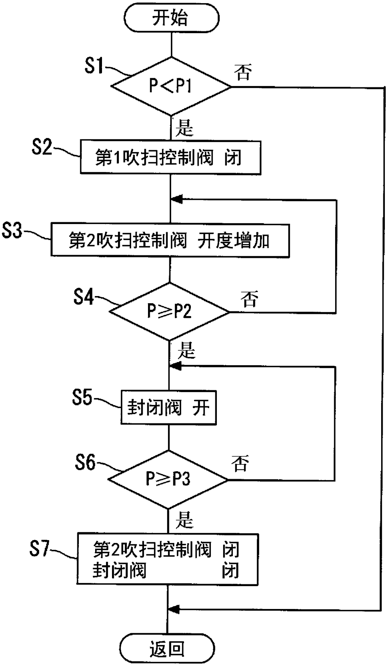
[0004] However, a relatively large solenoid valve is used for the shutoff valve in order to carry out smooth fuel supply. Therefore, if the shutoff valve is opened when the fuel tank becomes negative pressure as in Patent Document 1, the gas flows rapidly toward the fuel tank, and as a result , Abnormal noise is generated along with the rapid pressure fluctuation and gas flow in the fuel tank

Method used


Image

  • Evaporative Fuel Treatment Unit
  • Evaporative Fuel Treatment Unit
  • Evaporative Fuel Treatment Unit

Examples


Embodiment Construction

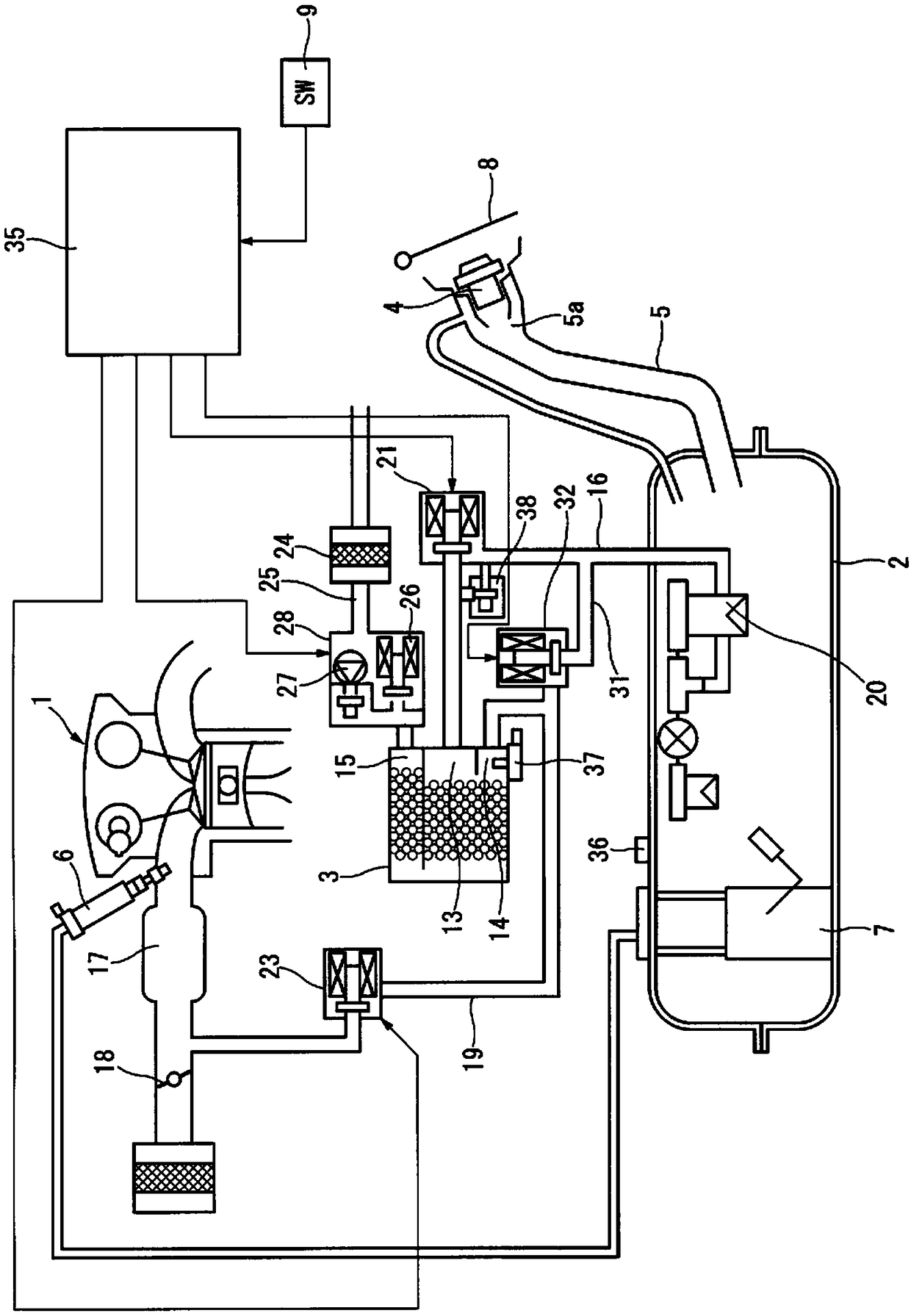
[0021] figure 1 It is an explanatory diagram showing the configuration of an embodiment of the evaporated fuel processing device of the present invention. An internal combustion engine 1 is mounted on a vehicle not shown in the figure, and an airtight fuel tank 2 is installed. In order to process the evaporated fuel generated in the fuel tank 2 during refueling, an evaporated fuel using a canister 3 is installed. Processing device. The above-mentioned fuel tank 2 is provided with a fuel supply pipe portion 5 for detachably attaching and fixing the filler hole cover 4 at the fuel supply port 5a at the top end, and also houses a fuel pump unit 7 for supplying fuel to the fuel injection device 6 of the internal combustion engine 1. Inside the fuel tank 2. The fuel supply port 5 a is covered with an electrically locked fuel cap 8 in order to restrict the opening of the filler cap 4 in a state where the pressure in the fuel tank 2 is high. The fuel cap 8 is unlocked in a state ...


PUM


Abstract

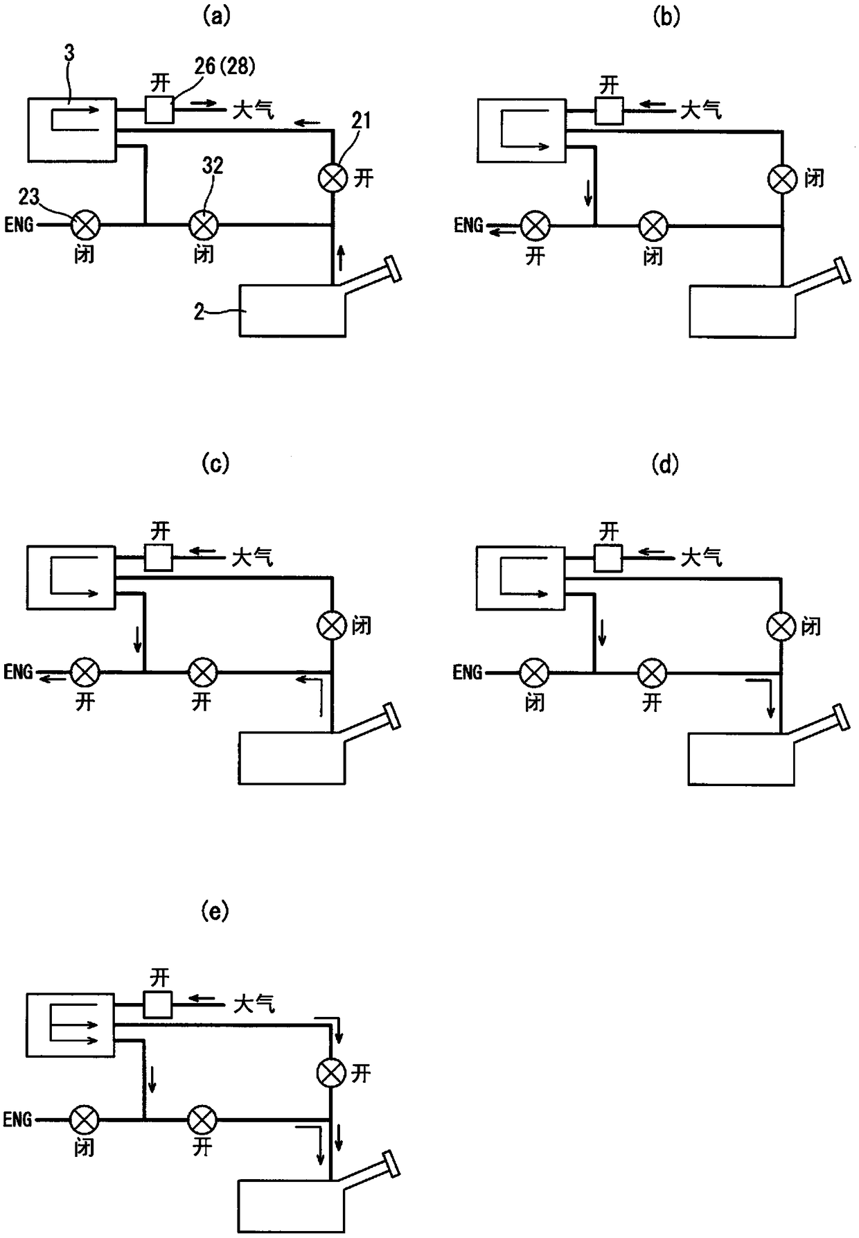
An evaporated fuel processing device includes: an evaporated fuel passage (16) connecting a fuel tank (2) and a canister (3); a purge passage (19) connecting the canister (3) and an intake passage (17) of an internal combustion engine (1); a first purge control valve (23) arranged to open and close the purge passage (19); a tank open passage (31) connecting a position on an upstream side of the first purge control valve (23) in the purge passage (19), and the tank (2); and a second purge control valve (32) arranged to open and close the tank open passage, when the fuel tank (2) becomes a negative pressure, the second purge control valve (32) being opened to introduce an atmospheric pressure through the canister (3).

Description

technical field [0001] The present invention relates to an evaporated fuel treatment device that uses an adsorption canister to treat evaporated fuel generated in a fuel tank during refueling, and particularly relates to a so-called closed fuel tank with a closing valve provided between the fuel tank and the adsorption canister Evaporative fuel handling unit. Background technique [0002] An evaporated fuel treatment device has been widely used in the past. In this evaporated fuel treatment device, in order to prevent the evaporated fuel generated in the fuel tank of the vehicle from flowing out to the outside, the evaporated fuel is temporarily adsorbed on an adsorbent using an adsorbent such as activated carbon. After that, during the operation of the internal combustion engine, due to the introduction of fresh air, the fuel components are purged from the adsorption tank and introduced into the intake system of the internal combustion engine. In addition, in recent years,...

Claims


Application Information

Patent Timeline
Patent Type & Authority Patents(China)
IPC IPC(8): F02M25/08
CPCB60K15/035F02M25/0818F02M25/0836F02M25/0872F02M25/089F02M2025/0845F02M25/08B60K15/03519B60K2015/03302
Inventor 渡边一央丰田一树大桥仁
Owner NISSAN MOTOR CO LTD
Learn More