Cam roller negative stiffness structure low-frequency vibration isolator

A cam roller and negative stiffness technology, applied in the field of vibration reduction and vibration isolation, can solve the problems of inconvenient installation of low-frequency vibration isolators, poor adaptability to working conditions, complex structure, etc., to reduce impact, ensure synchronization, and improve applicability Effect

Pending Publication Date: 2018-02-27
BEIJING MUNICIPAL INST OF LABOUR PROTECTION +1
View PDF12 Cites 13 Cited by
  • Summary
  • Abstract
  • Description
  • Claims
  • Application Information

AI Technical Summary

Problems solved by technology

[0011] The purpose of the present invention is to propose a low-frequency vibration isolator with a cam roller negative stiffness structure for the problems of inconvenient installation, complex structure, and poor adaptability to working conditions of the existing low-frequency vibration isolator.

Method used


Image

  • Cam roller negative stiffness structure low-frequency vibration isolator
  • Cam roller negative stiffness structure low-frequency vibration isolator
  • Cam roller negative stiffness structure low-frequency vibration isolator

Examples


Embodiment 1

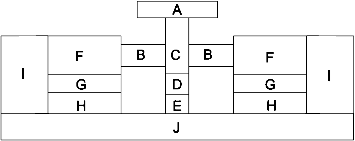
[0055] Such as figure 1 As shown, it is a structural block diagram of the system composition of a cam roller negative stiffness structure low-frequency vibration isolator of the present invention. Among them, the connection relationship of each component module is as follows:

[0056] The lower end of the center of the bearing device A is connected to the connecting cam C of the bearing platform, and the negative stiffness springs are connected to the cylindrical roller B on both sides of the connecting cam C of the bearing platform. The bottom connects and installs the positive stiffness spring D in the vertical direction and the positive stiffness spring positioning adjustment device E; the negative stiffness spring connects the cylindrical roller B with the negative stiffness spring structure F in the horizontal direction, and the negative stiffness spring structure F is connected with the negative stiffness spring positioning device G and The negative stiffness spring bot...

Embodiment 2

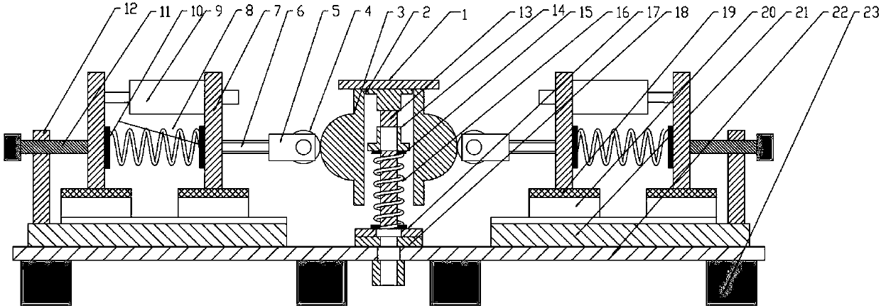
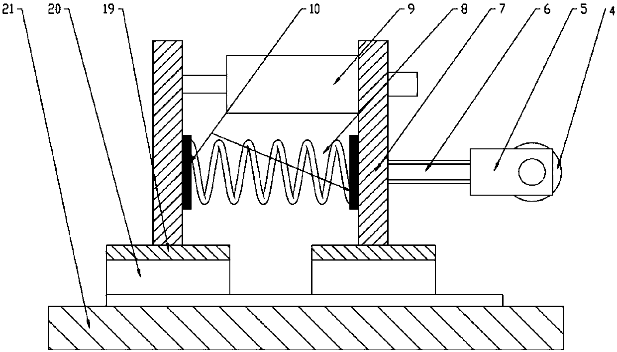
[0058] Such as Figure 2-5 shown; among them, figure 2 It is a structural schematic diagram of a low-frequency vibration isolator with a cam roller negative stiffness structure of the present invention; image 3 It is a structural schematic diagram of a negative stiffness structure in a cam roller negative stiffness structure low-frequency vibration isolator of the present invention; Figure 4 It is a structural schematic diagram of the connecting block of the horizontal spring bottom plate in a low-frequency vibration isolator with a cam roller negative stiffness structure of the present invention; Figure 5 It is a structural schematic diagram of a model bottom plate in a low-frequency vibration isolator with a cam roller negative stiffness structure of the present invention.

[0059] refer to figure 2 with image 3 , a cam roller negative stiffness structure low-frequency vibration isolator proposed in this embodiment includes a model base plate 22, and a model foot 2...

Embodiment 3

[0064] Figure 4 Shown is a structural schematic diagram of a cam roller negative stiffness structure low-frequency vibration isolator of this embodiment. The difference from Embodiment 2 is that the adjustment knob 11 for horizontal spring compression is adjusted. Adjusting the horizontal spring compression adjustment knob can realize the adjustment of the horizontal spring compression in the initial state, can change the negative stiffness value of the vibration isolator, and enhance the working condition adaptability of the vibration isolator.

[0065] Figure 5 It is the stiffness characteristic curve of a cam roller negative stiffness structure low-frequency vibration isolator of the present invention under different initial horizontal spring compressions. The parameter δ in the figure is the ratio of the horizontal spring compression to the sum of the radius of the cam and the cylindrical roller; x represents the displacement of the initial state; k represents the stif...


PUM


Abstract

The invention relates to a cam roller negative stiffness structure low-frequency vibration isolator. According to the low-frequency vibration isolator, a positive and negative stiffness parallel connection principle is adopted, a positive stiffness element and a negative stiffness element are connected in parallel, system resonance is restrained in combination with an added damping device, and protection is provided for drastic situations. A positive stiffness adjustment device and a negative stiffness adjustment device are used for realizing effective and accurate adjustment of the positive stiffness range and negative stiffness range to meet different bearing mass and vibration isolation requirements. The problems that an existing low-frequency vibration isolator is inconvenient to install, complex in structure, poor in work condition adaptability and the like are solved.

Description

technical field [0001] The invention relates to the technical field of vibration reduction and isolation, in particular to a low-frequency vibration isolator with a cam roller negative stiffness structure. Background technique [0002] At present, urban rail transit, as one of the most effective ways to relieve urban traffic pressure, has developed rapidly. However, the environmental vibration induced by it is becoming more and more serious: the impact of gravity loading on the track when the train is running will cause the vibration of the track structure, and the vibration will be transmitted to buildings, equipment, etc. along the sleepers, ballast bed, foundation, etc., which will cause serious environmental damage vibration. Among these environmental vibrations, low-frequency vibration is the difficulty of environmental vibration control. [0003] On the other hand, with the development of large-scale and lightweight power machinery, the flexibility of components cont...

Claims


Application Information

Patent Timeline
Patent Type & Authority Applications(China)
IPC IPC(8): F16F15/04F16F15/02
CPCF16F15/02F16F15/04
Inventor 刘彦琦曹东兴史晓峰张伟
Owner BEIJING MUNICIPAL INST OF LABOUR PROTECTION
Why Eureka
Try Eureka