Low-resistance flow-equalizing water pipe tee joint

A water pipe, low resistance technology, applied in the direction of pipes, branch lines, pipes/pipe joints/fittings, etc., can solve the problems of high product cost, difficulty in adjusting water flow, large resistance of water pipe tee, and achieve simplified structure and Installation process, broad market application prospects, unobstructed natural mixing effect

Inactive Publication Date: 2018-02-27
吴喜平
6 Cites 2 Cited by

AI-Extracted Technical Summary

Problems solved by technology

When performing water supply operations, the hydrostatic pressure in the main pipe 1 is high, and the hydrostatic pressure in the thinner branch pipe 2 is smaller. It flows out through the thinner branch pipe 2; when the water return operation is performed, the hydrostatic pressure in the main pipe 1 is small, and the static pressure in the thinner branch pipe 2 is large, and the water flows from the thinner branch pipe 2 to the main pipe 1; due to the static pressure, the water is vertical When the water flow enters the main pipe, it will be impacted by the original water flow in the main pipe parallel to the axis of the main pipe, which will inevitably create resistance to the water flow and cause a large amount of energy loss.
In addition, there is also energy loss when the hydrostatic pressure changes to the hydrodynamic pressure
Therefore, the resistance of the water pipe tee ...

Abstract

The invention relates to a low-resistance flow-equalizing water pipe tee joint. A main body is composed of a main pipe and thin branch pipes arranged on the main pipe, each thin branch pipe is composed of an inner pipe and an outer pipe which are the same in inner diameter, the main body is in an L-shaped natural bending shape, the inner pipes are fixedly arranged on the inner pipe wall of the main pipe, the outer pipes are arranged on the outer surface of the main pipe in an extending manner, during water supply, the inner pipes achieve the flow dividing pipe effect, water in the main pipe can enter the inner pipes according to the designed water amount, the flow direction is smoothly changed, then, water can flow out of the outer pipes, during water returning, the thin branch pipes achieve the backflow pipe effect, backflow water flows to the main pipe through the inner pipes along the walls of the thin branch pipes, the water flow direction is consistent with the flow direction in the main pipe, and non-resistance natural mixing is achieved. Due to removing of an adjusting valve, the process of converting static pressure into dynamic pressure does not exist, the work manner thatin the prior art, the static pressure is converted into the dynamic pressure is effectively overcome, the shortcomings that due to arrangement of the adjusting valve, the water flow resistance is large, the water speed uniformity is poor, energy consumption is large, the flow is difficult to control, the products difficultly meet the design requirements, and meet the market application are overcome effectively, and the very high practicability and the worshipful market application prospects are achieved.

Application Domain

Branching pipes

Technology Topic

Water pipeEngineering +7

Image

  • Low-resistance flow-equalizing water pipe tee joint
  • Low-resistance flow-equalizing water pipe tee joint

Examples

  • Experimental program(1)

Example Embodiment

[0011] The present invention will be further described below in conjunction with the accompanying drawings and typical embodiments.
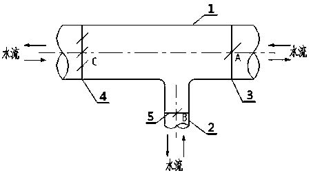
[0012] exist figure 1 Among them, the main body of the water pipe tee commonly used at present is composed of the main pipe 1 and the thinner branch pipe 2 arranged on the surface of the main pipe 1. Regulating valve A 3, regulating valve C 4 and regulating valve B 5 that control water flow are adjusted.
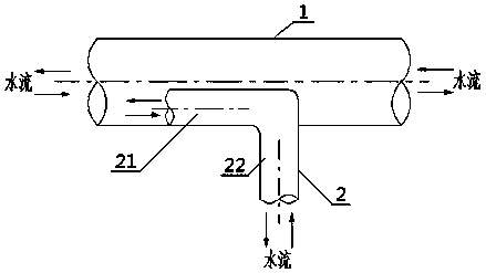
[0013] exist figure 2 Among them, the main body of the low-resistance flow equalizing water pipe tee of the present invention is composed of a main pipe 1 and a thinner branch pipe 2 arranged on the outer surface of the main pipe 1, which is characterized in that the main body of the thinner branch pipe 2 is in an L-shaped natural bending shape. An inner tube 21 fixed on the inner wall of the main tube in parallel with the main tube axis and an outer tube 22 stretched on the outer surface of the main tube 1, wherein the inner diameter of the inner tube 21 and the inner diameter of the outer tube 22 are the same ; The inner tube 21 is made of a thin stainless steel tube; the outer tube 22 is made of a thicker rigid pipe; during water supply, the inner tube 21 of the thinner branch pipe 2 acts as a shunt tube, and it flows from the main pipe to The water in the smaller branch pipe is driven by the total pressure of the water in the main pipe 1, and the water in the main pipe 1 enters the inner pipe 21 according to the design water volume determined by the cross-sectional area of ​​the inner pipe 21 lumen, and then flows out through the outer pipe 22, without static pressure fluctuations The process only changes the flow direction smoothly, does not change the water speed, the resistance is extremely small, and the energy consumption is extremely low; when returning water, the thinner branch pipe 2 acts as a return pipe, and the return water flows along the pipe wall of the thinner branch pipe 2 to the main pipe 1, When the water is out, the flow direction is ensured by the position and shape of the inner tube 21 on the thinner branch pipe 2 to be consistent with the flow direction in the cavity of the main pipe 1, and can naturally mix without resistance; in addition, the inner pipe of the thinner branch pipe 2 The angle between 21 and the L-shaped natural bending of the outer tube 22 is 10-90 degrees.

PUM

no PUM

Description & Claims & Application Information

We can also present the details of the Description, Claims and Application information to help users get a comprehensive understanding of the technical details of the patent, such as background art, summary of invention, brief description of drawings, description of embodiments, and other original content. On the other hand, users can also determine the specific scope of protection of the technology through the list of claims; as well as understand the changes in the life cycle of the technology with the presentation of the patent timeline. Login to view more.

Similar technology patents

Eight-station jack assembling machine

ActiveCN111168378AWork resistance is smallImprove disassembly efficiency
Owner:阳泉煤业华益机械有限公司

Graft and rapid propagation method for commercial production of Paeonia rockii

InactiveCN101473741AShorten the out-of-the-garden cyclereduce manufacturing cost
Owner:兰州牡丹园艺开发公司

Classification and recommendation of technical efficacy words

  • Work resistance is small

Eight-station jack assembling machine

ActiveCN111168378AWork resistance is smallImprove disassembly efficiency
Owner:阳泉煤业华益机械有限公司
Why Eureka
Try Eureka