
An inertial flywheel device with adjustable moment of inertia and automatic calibration

A technology of automatic calibration and moment of inertia, applied in measuring devices, flywheels, vibration suppression adjustment and other directions, can solve problems such as increasing service life, achieve low cost, save power source and control part, and increase working accuracy and service life. Effect

Active Publication Date: 2019-05-31
江阴智产汇知识产权运营有限公司
View PDF1 Cites 0 Cited by
  • Summary
  • Abstract
  • Description
  • Claims
  • Application Information

AI Technical Summary

Problems solved by technology

[0003] The purpose of the present invention is to address the above problems, and propose an inertial flywheel device with adjustable moment of inertia and automatic calibration, which can realize the function of simulating moment of inertia, and can adjust flywheel moment of inertia within a certain range to meet different requirements of the test. During the use of the flywheel, due to the abnormal vibration, noise and excessive dynamic load of the bearing caused by the uneven distribution of the flywheel mass, the moment of inertia can be automatically calibrated, and the problem of uneven distribution of the moment of inertia can be calibrated and adjusted during operation, eliminating the need for The cumbersome steps of disassembly, inspection and adjustment of the flywheel device can improve work efficiency, reduce the risk of component failure, and increase the service life of the device

Method used


Image

  • An inertial flywheel device with adjustable moment of inertia and automatic calibration
  • An inertial flywheel device with adjustable moment of inertia and automatic calibration
  • An inertial flywheel device with adjustable moment of inertia and automatic calibration

Examples


Embodiment Construction

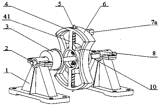
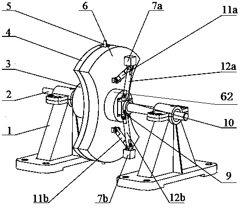
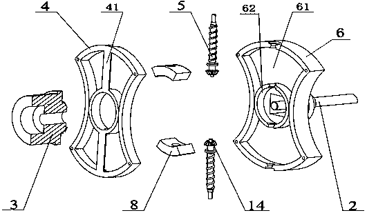
[0016] see figure 1 , 2 , 3, 4, the inertial flywheel device of the present invention has a flywheel shaft 2 arranged horizontally, and the two ends of the flywheel shaft 2 are respectively installed on the bearing housing 1 through rolling bearings, and can rotate around their central axis.

[0017] A bevel gear disc 3 and a flywheel disc 6 are sheathed on the flywheel shaft 2 , the bevel gear disc 3 and the flywheel disc 6 are arranged axially, and the bevel gear disc 3 can move axially along the flywheel shaft 2 . The central axes of the flywheel shaft 2, the bevel gear disc 3 and the flywheel disc 6 are collinear, that is, they have the same central axis. The bevel gear disc 3 has the function of adjusting the moment of inertia, and the flywheel disc 6 is equipped with components for adjusting the moment of inertia and calibrating the function of inertia.

[0018] The flywheel disc 6 is made of cast iron and is a fan-shaped disc symmetrical to the central axis. The middl...


PUM


Abstract

The invention discloses an inertial flywheel device adjustable in rotational inertia and capable of achieving automatic carlibaration. An annular bulge on a flywheel shaft is hollowly sleeved with themiddle of a flywheel disc, two lead screws which are symmetrical to each other around a center axis of the flywheel disc are radially arranged at one axial side of the flywheel disc, the inner end ofeach lead screw is provided with a small bevel gear at the inner side of the annular bulge, a mass block is assembled on each lead screw at the outer side of the annular bulge, and a bevel gear discis provided with conical teeth capable of being meshed with the two small bevel gears; the flywheel shaft is fixedly sleeved with an intermediate body, the intermediate body extends into a radial blind hole formed in the inner wall of the annular bulge through positioning columns with gaps, each positioning column is sleeved with a spiral spring, the other axial side surface of the flywheel disc is provided with two flywheel disc hinge bases, a mass adjusting block is hinged to each flywheel disc hinge base through a short connecting rod, and an intermediate body hinge base is hinged to each mass adjusting block through a long connecting rod; the magnitude of the rotational inertia can be continuously changed, and the uneven mass of a flywheel can be automatically sensed and adjusted.

Description

technical field [0001] The invention belongs to a mechanical device for experiment testing, and relates to a moment of inertia simulation device, in particular to an inertia flywheel structure with adjustable moment of inertia and automatic inertia calibration. Background technique [0002] The moment of inertia simulation device is widely used in experimental research fields such as automobile brakes, wind turbine simulators, and water turbine governors. The inertial flywheel device is widely used in the field of moment of inertia simulation because of its simple principle, stability and reliability. For the design of the inertia flywheel, it is necessary to meet the requirements of accurate and reliable moment of inertia, and at the same time, it is required that the inertia of the inertia simulator can be adjusted within a certain range to meet the needs of different moments of inertia in the test. Chinese patent application number CN201310625769.8 proposes an inertial f...

Claims


Application Information

Patent Timeline
Patent Type & Authority Patents(China)
IPC IPC(8): G01M1/30F16F15/31F16F15/315
CPCF16F15/31F16F15/3153F16F15/3156G01M1/30
Inventor 江洪王鹏程刘浩王子豪
Owner 江阴智产汇知识产权运营有限公司
Learn More