Heat management system and power supply device

A technology of thermal management system and pipeline, applied in the field of thermal management system and power supply device, can solve the problems of high requirements on machining precision of components, too many connections between flat tubes and main pipelines, high leakage risk, etc., so as to prevent thermal instability. , Excellent temperature control effect and small number of parts

Pending Publication Date: 2018-02-27
HUATING HEFEI POWER TECH
View PDF0 Cites 1 Cited by
  • Summary
  • Abstract
  • Description
  • Claims
  • Application Information

AI Technical Summary

Problems solved by technology

Traditional thermal management methods such as natural air cooling and evaporator air cooling can no longer meet market demand
In addition, the existing cylindrical liquid cooling schemes mostly use flat tubes interspersed between the modules to provide thermal management for the battery modules. This liquid cooling method has brought many effects while meeting the temperature control requirements. For example, grouping Complexity, high precision machining of parts, too many connections between flat tubes and main pipelines, resulting in a high potential leakage risk, which makes the temperature control effect of the battery module insufficient

Method used


Image

  • Heat management system and power supply device
  • Heat management system and power supply device
  • Heat management system and power supply device

Examples


Embodiment Construction

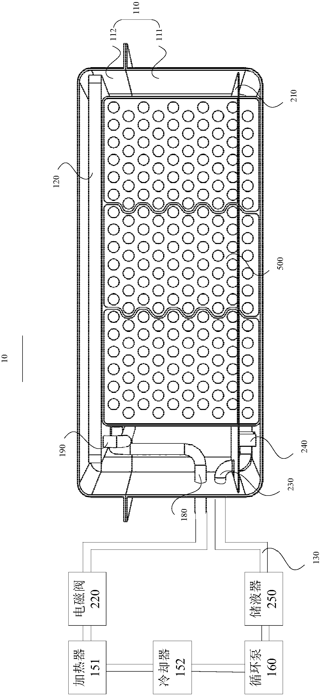
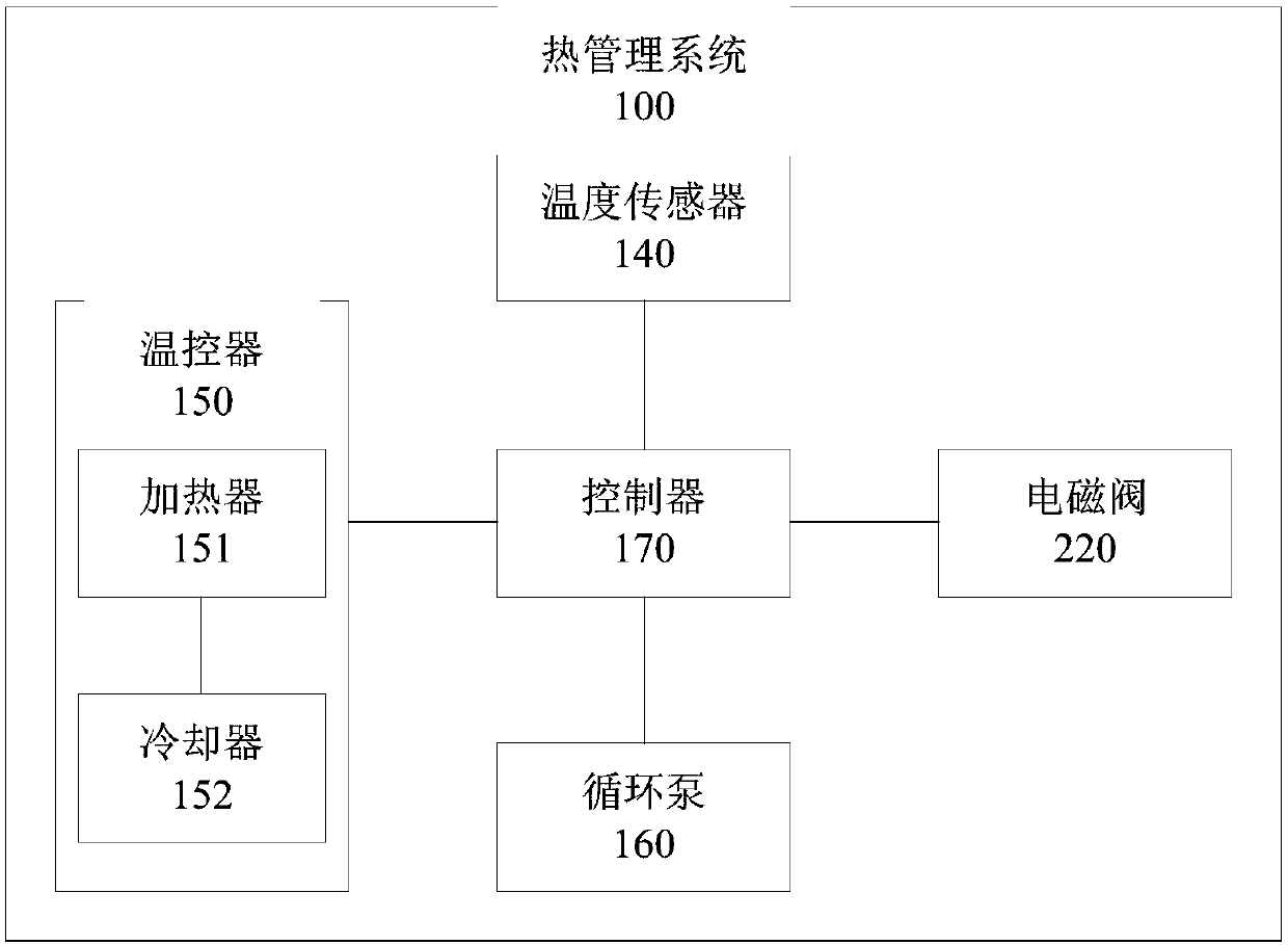
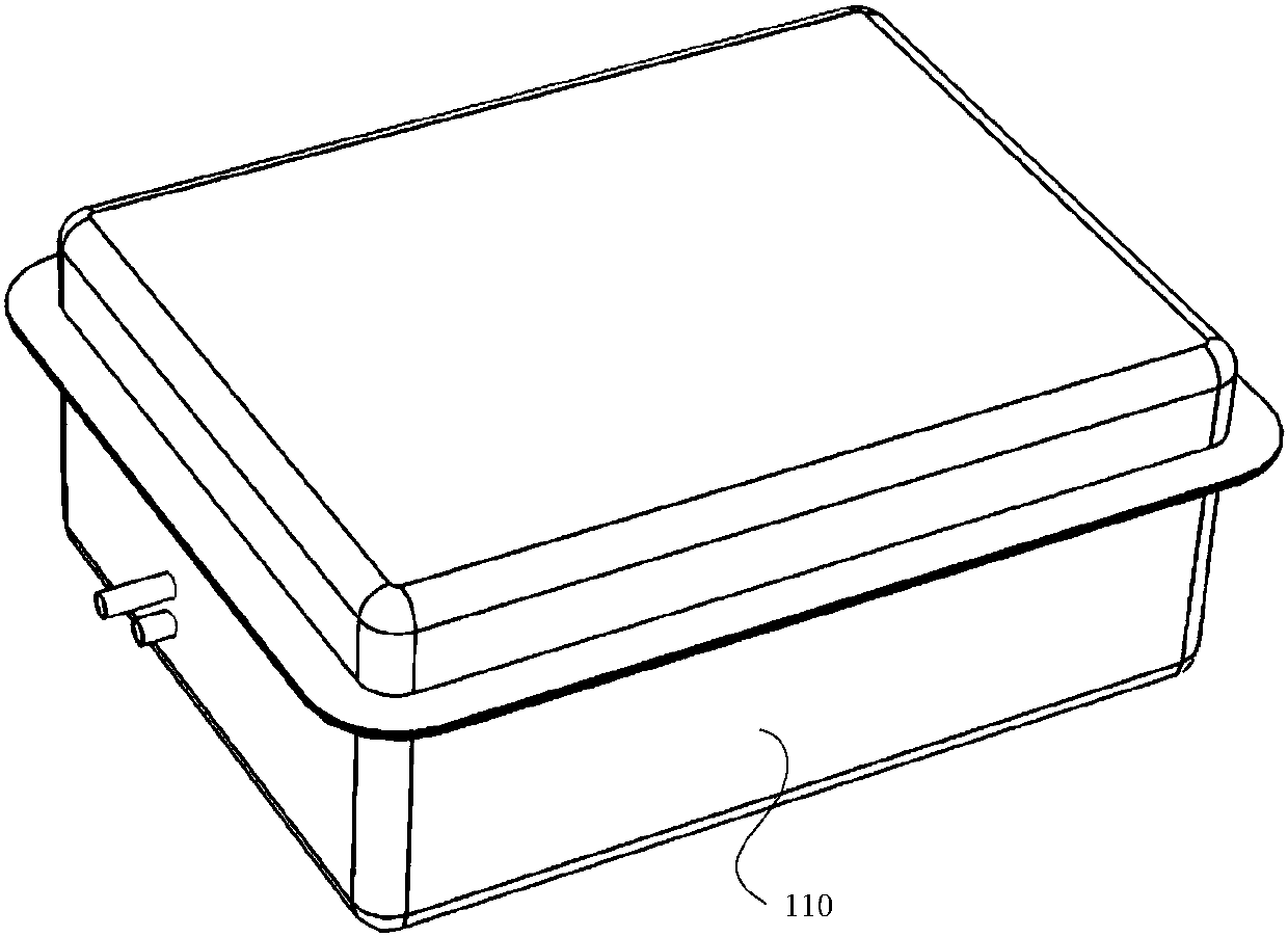
[0025] The following will clearly and completely describe the technical solutions in the embodiments of the present invention with reference to the drawings in the embodiments of the present invention. Apparently, the described embodiments are only some of the embodiments of the present invention, but not all of them. The components of the embodiments of the invention generally described and illustrated in the figures herein may be arranged and designed in a variety of different configurations. Accordingly, the following detailed description of the embodiments of the invention provided in the accompanying drawings is not intended to limit the scope of the claimed invention, but merely represents selected embodiments of the invention. Based on the embodiments of the present invention, all other embodiments obtained by those skilled in the art without making creative efforts belong to the protection scope of the present invention.

[0026] It should be noted that like numerals ...


PUM


Abstract

The invention relates to a heat management system and a power supply device. The heat management system comprises a shell, a spraying plate, a circulating pipeline, a temperature sensor, a temperaturecontroller, a circulating pump and a controller, wherein the spraying plate is arranged inside the shell, a liquid containing cavity is arranged inside the spraying plate, and a plurality of spray holes communicated with the liquid containing cavity are formed in the side wall of the spraying plate; the shell is provided with a first liquid inlet and a liquid outlet, and the first liquid inlet iscommunicated with the liquid containing cavity; one end of the circulating pipeline is communicated with the first liquid inlet and the other end of the circulating pipeline is communicated with theliquid outlet; the temperature sensor is arranged inside the shell and can be mounted to a battery module accommodated in the shell; the temperature controller and the circulating pump are arranged inthe circulating pipeline; and the controller is in communication connection with the temperature sensor, the temperature controller, and circulating pump. Compared with the prior art, the heat management system and the power supply device have the advantages of few parts, simplicity and convenience in mounting and excellent temperature control effect on the battery module.

Description

technical field [0001] The present invention relates to the technical field of temperature control of a power supply device, in particular to a thermal management system and a power supply device. Background technique [0002] With the increase in the energy density of lithium battery cells and the market's demand for fast charging of lithium batteries, the requirements for temperature control of lithium batteries after they are grouped are getting higher and higher. Traditional thermal management methods such as natural air cooling and evaporator air cooling can no longer meet market demand. In addition, the existing cylindrical liquid cooling schemes mostly use flat tubes interspersed between the modules to provide thermal management for the battery modules. This liquid cooling method has brought many effects while meeting the temperature control requirements. For example, grouping Complexity, high precision machining of components, too many connections between flat tubes...

Claims


Application Information

Patent Timeline
Patent Type & Authority Applications(China)
IPC IPC(8): H01M10/613H01M10/615H01M10/63H01M10/655H01M10/6568
CPCH01M10/613H01M10/615H01M10/63H01M10/655H01M10/6568Y02E60/10
Inventor 李德连劳力袁承超周鹏
Owner HUATING HEFEI POWER TECH
Why Eureka
Try Eureka