Guiding mechanism for hardware stamping die

A stamping die and guiding mechanism technology, applied in the direction of forming tools, manufacturing tools, metal processing equipment, etc., can solve the problems of mold protection, mold damage, inconvenient mold, etc., achieve high practical performance, simple structure, easy to adjust and fix Effect

Active Publication Date: 2018-03-02
柳州市钜嘉机械有限公司
View PDF7 Cites 11 Cited by
  • Summary
  • Abstract
  • Description
  • Claims
  • Application Information

AI Technical Summary

Problems solved by technology

[0002] As one of the high-efficiency production tools, metal stamping dies are widely used and important production equipment in industrial production. Using metal stamping dies to produce products and parts has the advantages of high production efficiency, which can achieve high-volume production and save Raw materials, to achieve the characteristics of non-cutting processing, the metal stamping die will use the guide mechanism to move the die in a certain direction during the stamping work, so that the die can accurately stamp the raw material, prevent the stamping position from shifting and cause defective products, during the stamping process If the position of the mold is not limited, the mold will contact the stamping platform after stamping the raw material and produce a certain amount of extrusion, which will easily cause damage or deformation of the mold and cause unnecessary losses, but the ordinary mold guiding mechanism can only Guide the mold, it is not convenient to limit the position of the mold, it cannot protect the mold, it is easy to cause damage to the mold, cause certain economic losses, and is not conducive to normal production work, so we propose a guide for metal stamping molds Institutions are used to solve the above problems

Method used


Image

  • Guiding mechanism for hardware stamping die
  • Guiding mechanism for hardware stamping die
  • Guiding mechanism for hardware stamping die

Examples


Embodiment

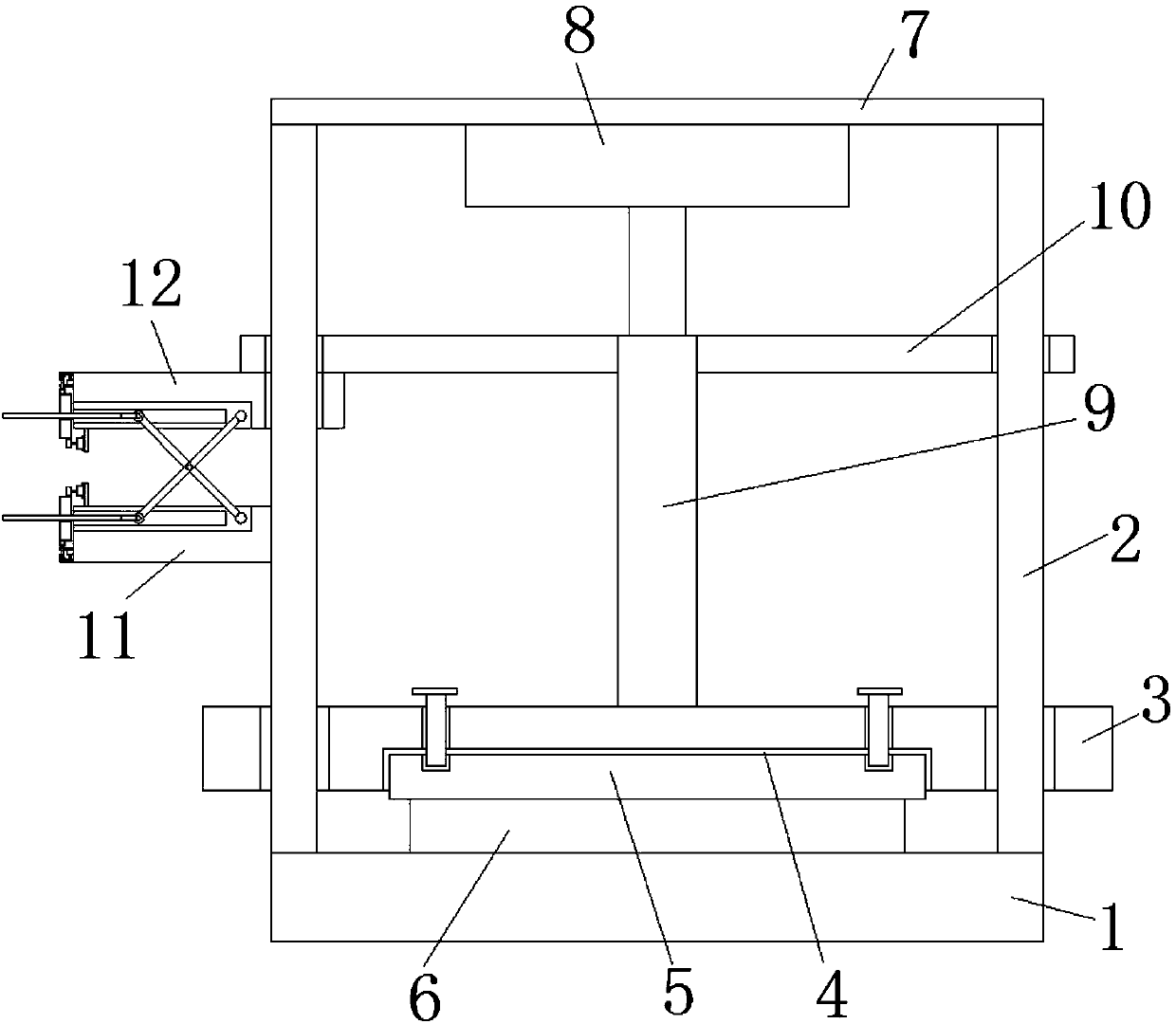
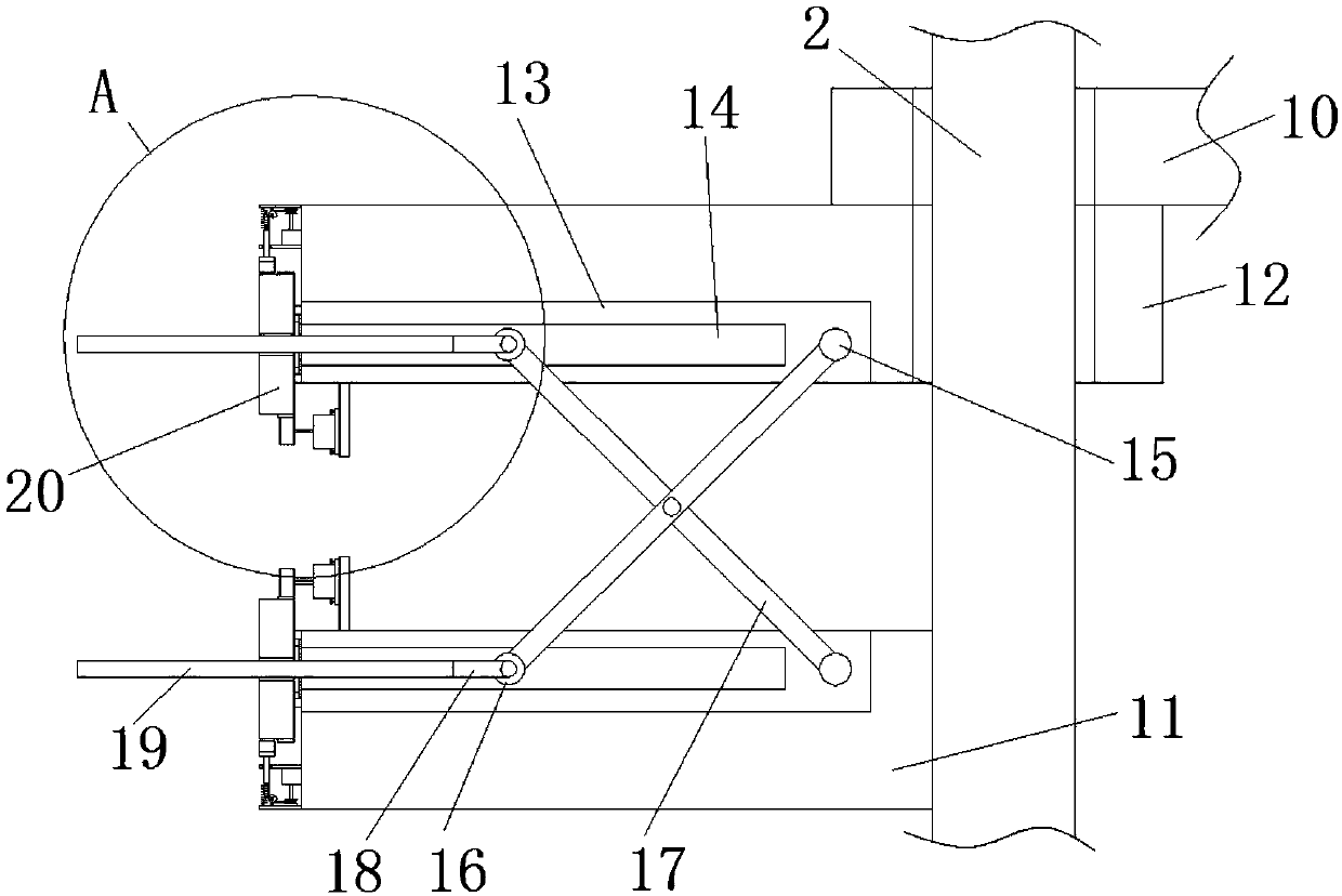
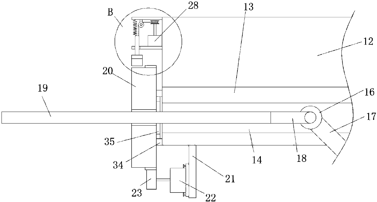
[0022] refer to Figure 1-5In this embodiment, a guide mechanism for a metal stamping die is proposed, including a stamping table 1, a guide column 2 is welded on both sides of the top of the stamping table 1, and the same lifting platform 3 is slidably installed on the two guide columns 2, The bottom of the lifting table 3 is provided with a mounting groove 4, and the internal thread of the mounting groove 4 is installed with a mounting plate 5. The bottom of the mounting plate 5 extends to the bottom of the lifting table 3 and is equipped with a mold body 6. The tops of the two guide columns 2 are welded with the same support plate 7, the bottom of the support plate 7 is fixedly installed with a hydraulic pump 8, the output shaft of the hydraulic pump 8 is welded with a drive rod 9, and the bottom of the drive rod 9 It is welded with the top of the lifting platform 3, and the outer sides of the two guide columns 2 are slidingly installed with limit rods 10, and the sides of ...


PUM


Abstract

The invention discloses a guiding mechanism for a hardware stamping die. The guiding mechanism for the hardware stamping die comprises a stamping table; guiding columns are welded to the two sides ofthe top of the stamping table, and a same lifting table is slidably mounted on the two guiding columns; a mounting groove is formed in the bottom of the lifting table, a mounting plate is mounted in the mounting groove in a threaded mode, and the bottom of the mounting plate extends to the lower portion of the lifting table and is provided with a die body; the bottom of the die body makes contactwith the top of the stamping table, a same supporting plate is welded to the top ends of the two guiding columns, and a hydraulic pump is fixedly mounted at the bottom of the supporting plate; and a driving rod is welded to an output shaft of the hydraulic pump, and the bottom of the driving rod and the top of the lifting table are welded. According to the guiding mechanism for the hardware stamping die, practical performance is high, the structure is simple, the height of a second positioning plate is conveniently adjusted and fixed, the descending position of the die body is limited throughthe second positioning plate so that extrusion between the die body and the stamping table cannot occur, and the die body can be protected.

Description

technical field [0001] The invention relates to the technical field of metal stamping die components, in particular to a guide mechanism of a metal stamping die. Background technique [0002] As one of the high-efficiency production tools, metal stamping dies are widely used and important production equipment in industrial production. Using metal stamping dies to produce products and parts has the advantages of high production efficiency, which can achieve high-volume production and save Raw materials, to achieve the characteristics of non-cutting processing, the metal stamping die will use the guide mechanism to move the die in a certain direction during the stamping work, so that the die can accurately stamp the raw material, prevent the stamping position from shifting and cause defective products, during the stamping process If the position of the mold is not limited, the mold will contact the stamping platform after stamping the raw material and produce a certain amount ...

Claims


Application Information

Patent Timeline
Patent Type & Authority Applications(China)
IPC IPC(8): B21D37/12B21D55/00
CPCB21D37/12B21D55/00
Inventor 王小华梁程鹏
Owner 柳州市钜嘉机械有限公司
Why Eureka
Try Eureka