
Device for spot welding of cells

A spot welding and cell technology, applied in auxiliary devices, welding equipment, auxiliary welding equipment, etc., can solve the problems of slow production process, increase labor, increase production cost, etc., to improve production efficiency, realize automatic production, and reduce production. cost effect

Active Publication Date: 2018-03-02
ANHUI TECHN COLLEGE OF MECHANICAL & ELECTRICAL ENG
View PDF7 Cites 6 Cited by
  • Summary
  • Abstract
  • Description
  • Claims
  • Application Information

AI Technical Summary

Problems solved by technology

[0002] With the continuous development of electronic products and people's use of electronic products more and more, the use of batteries is also increasing. The spot welding of batteries is an indispensable link in the production of batteries, and now Most of the electric core spot welding process is manual spot welding, and its slow production process also increases labor and increases production costs. However, most of the existing spot welding equipment for electric cores manually feed the fixture, and then the treatment The tools are installed on the spot welding equipment, and then the spot welding is realized by machinery. These equipments only realize the automation of part of the procedures in the spot welding process, but still need some manual work to feed and install the jigs. For the above problems, a device for electric core spot welding is provided, which can realize automatic feeding of jigs and automatic spot welding process

Method used


Image

  • Device for spot welding of cells
  • Device for spot welding of cells
  • Device for spot welding of cells

Examples


Embodiment Construction

[0029] Below in conjunction with accompanying drawing and embodiment of description, specific embodiment of the present invention is described in further detail:

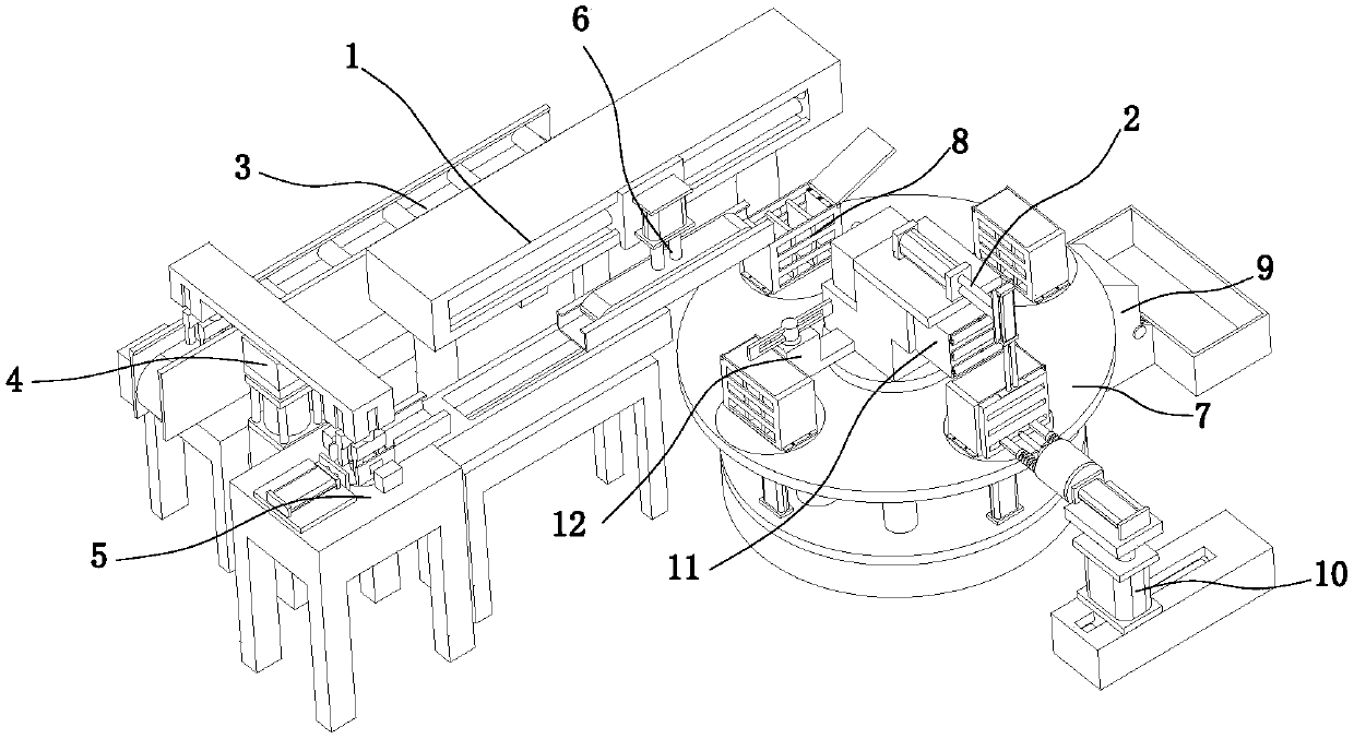
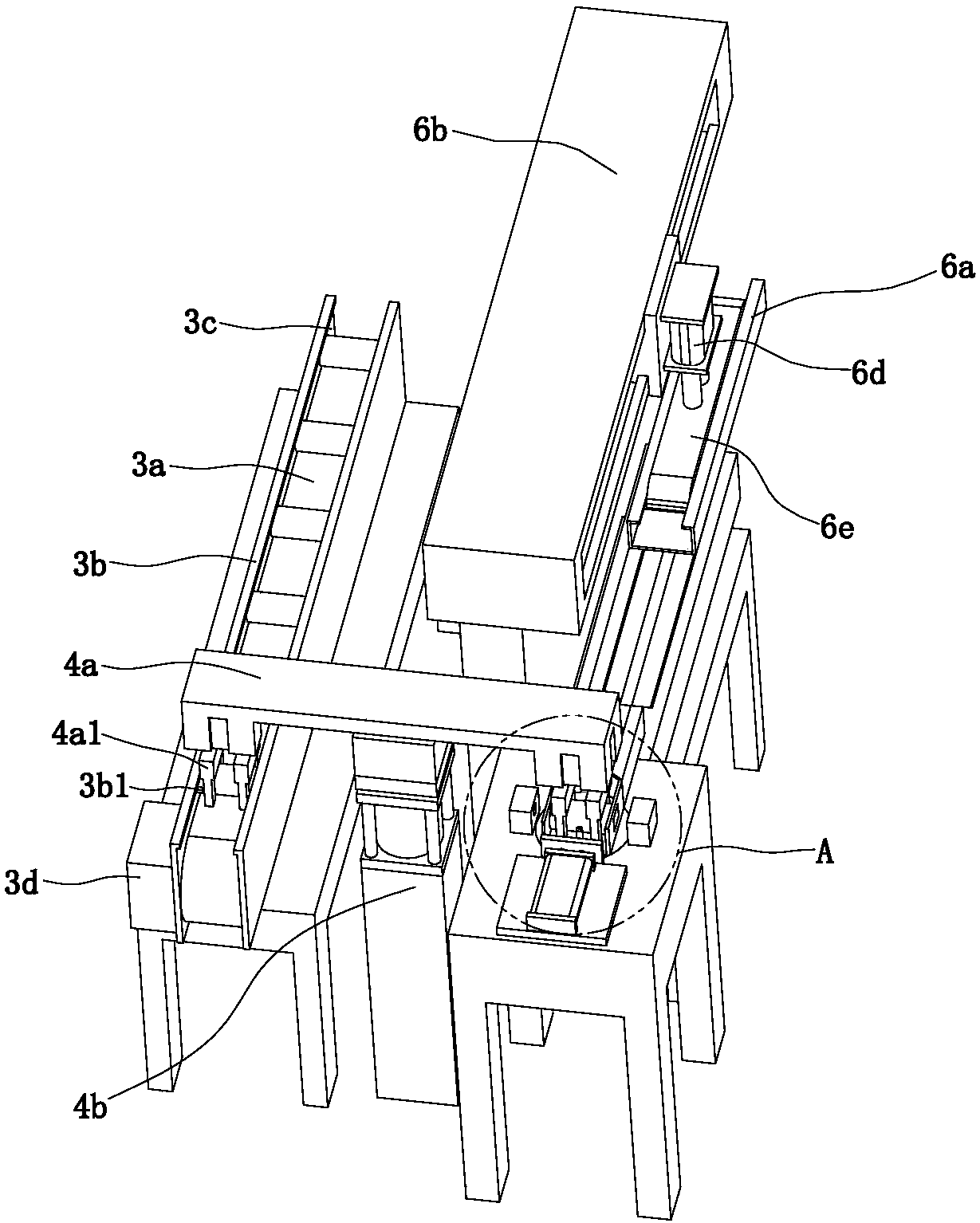
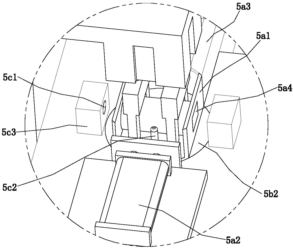
[0030] refer to Figure 1 to Figure 12 A kind of device that is used for electric core spot welding shown, comprises feeding mechanism 1 and spot welding mechanism 2, and feeding mechanism 1 is positioned at the side of spot welding mechanism 2, and described feeding mechanism 1 includes conveying device 3, transfer Device 4, detection device 5 and blanking device 6, transfer device 4 is positioned at one side of transfer device 3, detection device 5 is positioned at the other side of transfer device 4, detection device 5 is fixedly connected with blanking device 6, described spot welding Mechanism 2 comprises rotating device 7, feeding device 8, unloading device 9, spot welding device 10 and sheet metal feeding device 11, and feeding device 8 is circumferentially distributed in the edge place of rotating device 7, ...


PUM


Abstract

The present invention relates to the field of battery spot welding, and especially relates to a device for spot welding of cells. The device comprises a feed mechanism and a spot welding mechanism. The feed mechanism comprises a conveyor device, a transfer device, a detection device and a blanking device. The spot welding mechanism comprises a rotating device, a transporting device, an unloading device, a spot welding device and a metal sheet feed device. Cells are conveyed to the detection device by the conveyor device and the transfer device for detection of anode and cathode directions of the cells, the anode and cathode directions of the cells are adjusted to be consistent, the cells are installed into jigs by the blanking device and successively rotated with 90 degrees by the rotatingdevice, three steps of closing a feed door, spot welding and blanking are implemented side by side, and spot welding processes of the cells are achieved. During the processes, the anode and cathode directions of the cells and automatic spot welding of the spot welding mechanism are automatically detected and adjusted by the feed mechanism, automatic production is achieved, manpower is saved, production efficiency is improved, and production cost is reduced.

Description

technical field [0001] The invention relates to the field of battery spot welding, in particular to a device for battery spot welding. Background technique [0002] With the continuous development of electronic products and people's use of electronic products more and more, the use of batteries is also increasing. The spot welding of batteries is an indispensable link in the production of batteries, and now Most of the electric core spot welding process is manual spot welding, and its slow production process also increases labor and increases production costs. However, most of the existing spot welding equipment for electric cores manually feed the fixture, and then the treatment The tools are installed on the spot welding equipment, and then the spot welding is realized by machinery. These equipments only realize the automation of part of the procedures in the spot welding process, but still need some manual work to feed and install the jigs. To solve the above problems, a...

Claims


Application Information

Patent Timeline
IPC IPC(8): B23K37/00
CPCB23K37/00
Inventor 李庆孙伟方慧敏吴亚兰胡如方赵文英孙灏王福康韩鹏鑫黄浩郝俊泽
Owner ANHUI TECHN COLLEGE OF MECHANICAL & ELECTRICAL ENG
Learn More