Automatic guitar polishing device

A guitar, automatic technology, used in grinders, belt grinders, grinding/polishing equipment, etc., can solve the problems of poor manual grinding environment, short service life of abrasive belts, difficult installation of abrasive belts, etc. The effect of long service life of abrasive belt and high grinding efficiency

Inactive Publication Date: 2018-03-02
贵州金韵乐器有限公司
View PDF0 Cites 6 Cited by
  • Summary
  • Abstract
  • Description
  • Claims
  • Application Information

AI Technical Summary

Problems solved by technology

[0002] At present, the grinding device used in guitar production uses two rollers to drive the abrasive belt for grinding. However, after the abrasive belt is used for a period of time, the abrasive belt will become loose, and the pressure between the abrasive belt and the rollers will decrease. There will be slippage and cannot be used normally; due to the length error of the abrasive belt of the grinding device, the distance between the rollers needs to be continuously adjusted during installation. If the distance between the rollers is too short, the abrasive belt is easy to slip, and the distance between the rollers is too long. The abrasive belt is easily damaged, the installation of the abrasive belt is complicated, and the service life is short; in the guitar grinding device, the degree of automation is low, the manual grinding environment is poor, the grinding flatness is low, the workload is large, and the grinding efficiency is low
[0003] To sum up, in the prior art, the abrasive belt is prone to slipping, the installation of the abrasive belt is difficult, the accuracy of the length of the abrasive belt is high, the service life of the abrasive belt is short, the degree of automation is low, the manual grinding environment is poor, and the grinding flatness is low , the workload is heavy, and the technical problems of grinding work efficiency are low

Method used


Image

  • Automatic guitar polishing device

Examples


Embodiment Construction

[0013] The present invention will be further described below in conjunction with the accompanying drawings and embodiments, but not as a basis for limiting the present invention.

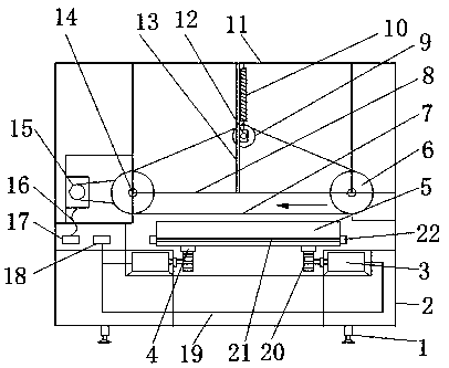
[0014] Example. An automatic guitar polishing device, constituted as figure 1 As shown, a box body 2 is included, the bottom of the lower end of the box body 2 is connected with a support seat 1, a first roller 14 is arranged in the upper end of the box body 2, and a first motor 15 is connected to one side of the first roller 14. The two sides of 14 are connected with horizontal connecting rod 8, and the other end of two horizontal connecting rods 8 is connected with the second roller 6 opposite to the inner side, and the middle position of horizontal connecting rod 8 is connected with vertical sliding rod 13, and the other end of vertical sliding rod 13 The fixed rod 11 is connected, the vertical sliding rod 13 is connected with the slider 12 through the chute, the slider 12 is connected with the ...


PUM


Abstract

The invention discloses an automatic guitar polishing device. It includes a box body, a first roller is arranged inside the upper end of the box body, horizontal connecting rods are connected to both sides of the first roller, a vertical sliding rod is connected to the middle of the horizontal connecting rod, and a fixed rod is connected to the other end of the vertical sliding rod. The vertical slide bar is connected with a slide block through a chute, the slide block is connected with the fixed bar through a spring, and a third roller is connected to the inner side of the slide block on the two vertical slide bars; a guitar mold is arranged below the horizontal connecting bar, Both sides of the bottom of the guitar mold are provided with a rack, the rack is connected with a gear, and the gear is connected with a second motor; the first, second and third drums are wound with abrasive belts. The invention has the advantages that the abrasive belt is not easy to slip, the installation of the abrasive belt is simple, the accuracy of the length of the abrasive belt is low, the service life of the abrasive belt is long, the degree of automation is high, the manual grinding environment is good, the grinding flatness is high, and the workload is small. Beneficial effect of high sanding work efficiency.

Description

technical field [0001] The invention relates to a polishing device, in particular to an automatic guitar polishing device. Background technique [0002] At present, the grinding device used in guitar production uses two rollers to drive the abrasive belt for grinding. However, after the abrasive belt is used for a period of time, the abrasive belt will become loose, and the pressure between the abrasive belt and the rollers will decrease. There will be slippage and cannot be used normally; due to the length error of the abrasive belt of the grinding device, the distance between the rollers needs to be continuously adjusted during installation. If the distance between the rollers is too short, the abrasive belt is easy to slip, and the distance between the rollers is too long. The abrasive belt is easily damaged, the installation of the abrasive belt is complicated, and the service life is short; in the grinding device of the guitar, the degree of automation is low, the manua...

Claims


Application Information

Patent Timeline
Patent Type & Authority Applications(China)
IPC IPC(8): B24B21/00B24B21/18
CPCB24B21/006B24B21/18
Inventor 刘江波
Owner 贵州金韵乐器有限公司
Why Eureka
Try Eureka