Robot and method for identifying road block through robot

A robot and steering gear technology, applied in the field of robots, can solve problems such as difficulty in meeting requirements, inability to identify the types of roadblocks, inability to distinguish sweeping robots, etc., to achieve the effects of convenient disassembly and assembly, stable connection and stable structure

Active Publication Date: 2018-03-02
南京微米信息科技有限公司
7 Cites 3 Cited by

AI-Extracted Technical Summary

Problems solved by technology

[0003] The sweeping robot is one of the most household robots at present, but the existing sweeping robot cannot recognize the types of roadb...

Method used

The beneficial effect of present embodiment is: when encountering obstacle, by adopting first distance sensor, second distance sensor and the 3rd distance sensor to the both sides of obstacle and upper end point detection and cooperate thermal detector and then can Effectively identify whether the obstacle is a stationary object or an animal, the coupling is located at the end of the third distance sensor, the third distance sensor is located on the driving device, the third distance sensor and the coupling are integrated, the third distance sensor and the coupling The shaft device is a whole with a stable structure. The first distance sensor is embedded in the driving device, and the obstacle detection sensor adopts an embedded structure, which can effectively prevent the obstacle detection sensor from being damaged. The bottom surface of the steering gear and the encoder are both provided with an insertion part, the end of the insertion part is provided with a first magnet, the top of the driving device is provided with an insertion hole matching the insertion part, and the bottom of the insertion hole is provided with a second magnet, and the insertion part is inse...

Abstract

The invention discloses a robot and a method for identifying a road block through the robot. The robot comprises a driving device, a control device and an identifying system. A first storage trough, asecond storage trough, a steering engine and an encoder are arranged on the driving device, a first electric push rod and a second electric push rod are arranged in the first storage trough and the second storage trough correspondingly, and a first electric rotary table and a second electric rotary table are arranged at the tail ends of the first electric push rod and the second electric push rodcorrespondingly; and the identifying system comprises a road block detecting sensor, a heat detector, a first range sensor, a second range sensor and a third range sensor, the first range sensor andthe second range sensor are fixedly connected with the first electric rotary table and the second electric rotary table correspondingly, couplings are arranged on the third range sensor, and the steering engine and the encoder are fixedly connected with the third range sensor through the couplings. The robot has the function of identifying the road block.

Application Domain

Technology Topic

Image

  • Robot and method for identifying road block through robot
  • Robot and method for identifying road block through robot

Examples

  • Experimental program(2)

Example Embodiment

[0027] Example 1
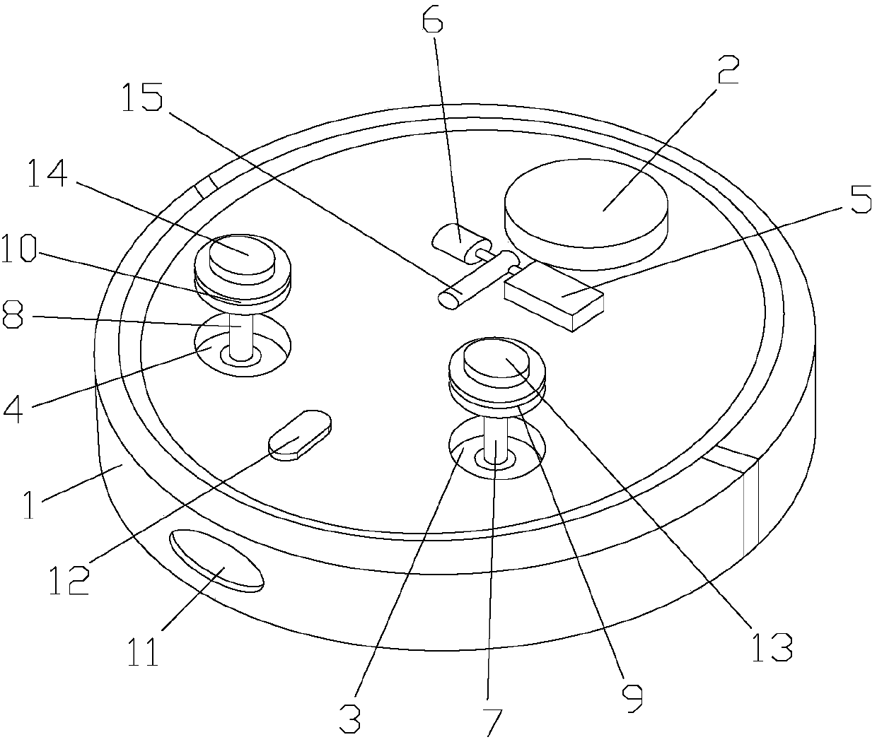
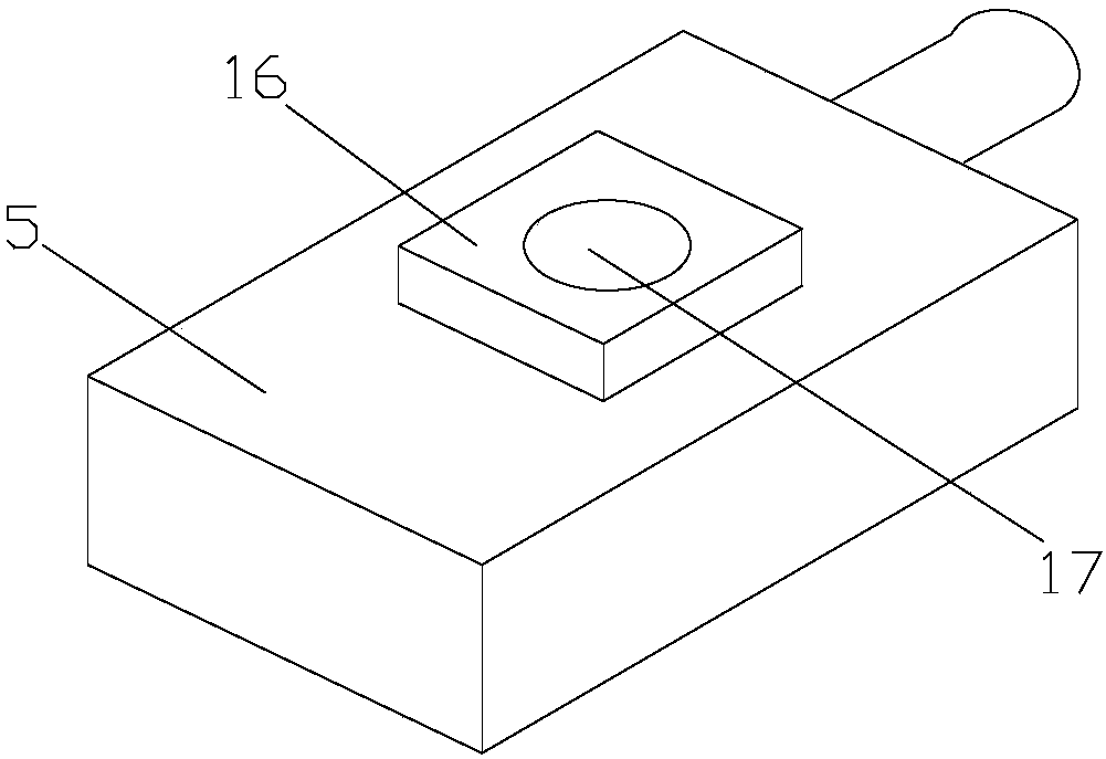
[0028] Such as Figure 1-2 As shown, a robot includes a driving device 1, a control device 2, and an identification system. The driving device 1 is provided with a first storage slot 3, a second storage slot 4, a steering gear 5, and an encoder 6. The first storage tank 3 and the second storage tank 4 are respectively provided with a first electric push rod 7 and a second electric push rod 8, and the ends of the first electric push rod 7 and the second electric push rod 8 are respectively arranged There are a first electric turntable 9 and a second electric turntable 10. The identification system includes an obstacle detection sensor 11, a heat detector 12, a first distance sensor 13, a second distance sensor 14 and a third distance sensor 15. The first distance sensor 13 and the second distance sensor 14 are respectively fixedly connected to the first electric turntable 9 and the second electric turntable 10, and the third distance sensor 15 is provided with a coupling (not shown), the steering gear 5 and the encoder 6 are fixedly connected to the third distance sensor 15 through a coupling. The obstacle detection sensor 11, the heat detector 12 and the third distance sensor 15 are located on the same straight line, and the first electric push rod 7. The second electric push rod 8, the first electric turntable 9, the second electric turntable 10, the obstacle detection sensor 11, the heat detector 12, the first distance sensor 13, the second distance sensor 14 and the third distance sensor 15 are all It is electrically connected to the control device 2. When encountering an obstacle, the first distance sensor 13, the second distance sensor 14 and the third distance sensor 15 are used to detect the two sides and upper end of the obstacle and cooperate with the heat detector 12 to effectively identify the obstacle. Stationary objects are still animals.
[0029] The beneficial effect of this embodiment is that when an obstacle is encountered, the first distance sensor, the second distance sensor, and the third distance sensor are used to detect both sides and upper ends of the obstacle and cooperate with the heat detector to effectively identify the obstacle. Whether the obstacle is a static object or an animal.

Example Embodiment

[0030] Example 2
[0031] Such as Figure 1-2 As shown, a robot includes a driving device 1, a control device 2, and an identification system. The driving device 1 is provided with a first storage slot 3, a second storage slot 4, a steering gear 5, and an encoder 6. The first storage tank 3 and the second storage tank 4 are respectively provided with a first electric push rod 7 and a second electric push rod 8, and the ends of the first electric push rod 7 and the second electric push rod 8 are respectively arranged There are a first electric turntable 9 and a second electric turntable 10. The identification system includes an obstacle detection sensor 11, a heat detector 12, a first distance sensor 13, a second distance sensor 14 and a third distance sensor 15. The first distance sensor 13 and the second distance sensor 14 are respectively fixedly connected to the first electric turntable 9 and the second electric turntable 10, and the third distance sensor 15 is provided with a coupling (not shown), the steering gear 5 and the encoder 6 are fixedly connected to the third distance sensor 15 through a coupling. The obstacle detection sensor 11, the heat detector 12 and the third distance sensor 15 are located on the same straight line, and the first electric push rod 7. The second electric push rod 8, the first electric turntable 9, the second electric turntable 10, the obstacle detection sensor 11, the heat detector 12, the first distance sensor 13, the second distance sensor 14 and the third distance sensor 15 are all It is electrically connected to the control device 2. The coupling is located at the end of the third distance sensor 15, the third distance sensor 15 is located above the driving device 1, the third distance sensor 15 and the coupling are integrated, and the third distance sensor 15 is connected to the coupling The device is a whole and the structure is stable. The obstacle detection sensor 11 is embedded in the driving device 1 and the obstacle detection sensor 11 adopts an embedded structure, which can effectively prevent the obstacle detection sensor 11 from being damaged. Both the steering gear 5 and the encoder 6 are provided with an insertion portion 16 on the bottom surface, the end of the insertion portion 16 is provided with a first magnet 17, and the driving device 2 is provided with an insertion hole (not shown) matching the insertion portion 16 (Shown), the bottom of the insertion hole is provided with a second magnet (not shown), the insertion portion 16 is inserted into the insertion hole, the steering gear 5 and the encoder 6 are both easy to disassemble and assemble with the drive device 1, and the connection is stable. The head ends of the first electric push rod 7 and the second electric push rod 8 are glued to the bottom of the first storage tank 3 and the second storage tank 4 respectively. The first electric push rod 7 and the second electric push rod 8 are connected to the bottom of the storage tank stably. The first distance sensor 13 and the second distance sensor 14 are both provided with a tenon (not shown) underneath, and the first distance sensor 13 and the second distance sensor 14 are glued to their respective tenons, and the first Both the electric turntable 9 and the second electric turntable 10 are provided with a mortise (not shown) matched with a tenon. The first distance sensor 13 and the second distance sensor 14 are respectively connected to the first electric turntable 9 and the second electric turntable 10 Tenon and tenon connection, the sensor and the electric turntable are combined with each other to support each other, and the force performance is stable. The first storage tank 3 and the second storage tank 4 are symmetrically distributed. The control device 2 is located on the drive device 1, and the drive device 1 is connected with the control device 2 by bolts. The control device 2 is easy to disassemble and assemble, which can facilitate the maintenance of workers. When encountering an obstacle, the first distance sensor 13, the second distance sensor 14 and the third distance sensor 15 are used to detect the two sides and upper end of the obstacle and cooperate with the heat detector 12 to effectively identify the obstacle. Stationary objects are still animals.
[0032] The beneficial effect of this embodiment is that when an obstacle is encountered, the first distance sensor, the second distance sensor, and the third distance sensor are used to detect both sides and upper ends of the obstacle and cooperate with the heat detector to effectively identify the obstacle. Whether the obstacle is a stationary object or an animal, the coupling is located at the end of the third distance sensor, the third distance sensor is located on the drive device, the third distance sensor and the coupling are integrated, and the third distance sensor and the coupling are As a whole, the structure is stable. The first distance sensor is embedded in the driving device, and the obstacle detection sensor adopts an embedded structure, which can effectively prevent the obstacle detection sensor from being damaged. Both the steering gear and the encoder are provided with an insertion part on the bottom surface. The end of the insertion part is provided with a first magnet. The driving device is provided with an insertion hole matching the insertion part. The bottom of the insertion hole is provided with a second magnet. In the hole, the steering gear and encoder are easy to disassemble and assemble with the driving device, and the connection is stable. The head ends of the first electric push rod and the second electric push rod are respectively glued to the bottom of the first storage slot and the second storage groove. The first electric push rod and the second electric push rod are both connected to the groove of the storage slot. The bottom connection is stable. Both the first distance sensor and the second distance sensor are provided with a tenon underneath, the first distance sensor and the second distance sensor are glued to their respective tenons, and the first electric turntable and the second electric turntable are both provided with a tenon pairing The mortise, the first distance sensor and the second distance sensor are respectively connected with the first electric turntable and the second electric turntable tenon and tenon, the sensor and the electric turntable are combined with each other and support each other, and the force performance is stable. The control device is located on the drive device, and the drive device is bolted to the control device. The control device is easy to disassemble and assemble, which can facilitate the maintenance of the staff.
[0033] Another technical problem to be solved by the present invention is to provide a method for robots to identify roadblocks, which includes the following steps:
[0034] 1) Use obstacle detection sensors for detection;
[0035] 2) When the obstacle detection sensor detects an obstacle in front of the drive device, it will feed back the signal to the control device, and then stop working;
[0036] The control device stops the driving device to advance and turns on the first electric push rod and the second electric push rod to raise the first distance sensor and the second distance sensor, using the first electric turntable and the second electric turntable from the left and right sides of the driving device Start to continuously detect the direction of the obstacle detected by the obstacle detection sensor until the two sides of the obstacle are detected;
[0037] At the same time, the control device turns on the heat detector to detect obstacles;
[0038] At the same time, the control device turns on the steering gear to drive the third distance sensor to lift up and detect the distance between the third distance sensor and the upper end of the obstacle, and then feedback the detected distance and the angular displacement of the third distance sensor detected by the encoder to the control device ;
[0039] 4) If the first distance sensor, the second distance sensor and the third distance sensor still detect obstacles after 3-5 seconds and the heat detector does not receive infrared radiation, it is recognized as a stationary obstacle;
[0040] If the heat detector receives infrared radiation, it is recognized as an animal.

PUM

no PUM

Description & Claims & Application Information

We can also present the details of the Description, Claims and Application information to help users get a comprehensive understanding of the technical details of the patent, such as background art, summary of invention, brief description of drawings, description of embodiments, and other original content. On the other hand, users can also determine the specific scope of protection of the technology through the list of claims; as well as understand the changes in the life cycle of the technology with the presentation of the patent timeline. Login to view more.

Similar technology patents

Classification and recommendation of technical efficacy words

  • Stable structure
  • Prevent crash

Sounder

Owner:AAC ACOUSTIC TECH (SHENZHEN) CO LTD +1
Why Eureka
Try Eureka