A method for drone aircraft image calibration for slope surface measurement

An image calibration and slope technology, applied in image analysis, measurement device, image data processing and other directions, can solve the problems of inability to obtain real-time, poor timeliness, many differences, etc., to improve the accuracy and calibration efficiency, and the calibration method is simple. , the effect of high accuracy

Active Publication Date: 2021-01-19
成都准望科技有限公司
View PDF7 Cites 0 Cited by
  • Summary
  • Abstract
  • Description
  • Claims
  • Application Information

AI Technical Summary

Problems solved by technology

[0003] UAV orthophoto measurement technology is only used in flat areas. In hilly and hillside areas, due to the particularity of the landform, the accuracy of the measurement results decreases, and even only the projected area can be obtained. The final result is quite different from the actual data;
[0004] The oblique photography technology can perform aerial calibration on the slope, which reorganizes the point cloud of multi-angle aerial pictures to obtain a 3D model for slope calibration and measurement; this method needs to collect a large number of multi-angle aerial pictures in the early stage, and through professional construction. The results can only be obtained after several hours of processing by the modeling software and graphics workstation. Although the accuracy is high, the timeliness is poor, and the data that can be used for measurement cannot be obtained in real time. In addition, the cost of purchasing professional equipment is as high as hundreds of thousands, and professional Only personnel can complete the operation, which is undoubtedly a high threshold for lightweight users

Method used


Image

  • A method for drone aircraft image calibration for slope surface measurement
  • A method for drone aircraft image calibration for slope surface measurement
  • A method for drone aircraft image calibration for slope surface measurement

Examples


Embodiment 1

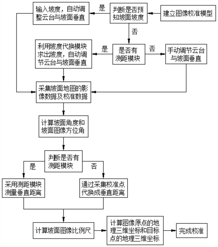
[0104] Such as figure 2 As shown, a UAV aerial image calibration method suitable for slope measurement includes the following steps:

[0105] a. Establish an image calibration model with four parameters: slope angle Slope, slope image azimuth angle Azimuth, slope image scale SlopeScale, and image origin Origin;

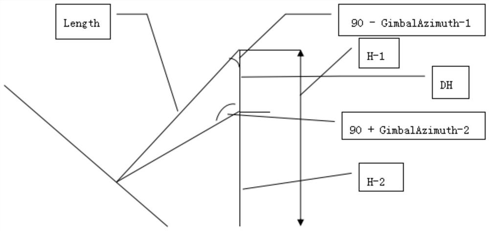
[0106] b. Acquisition of slope images including exposure point pitch angle GimbalPitch-1, exposure point azimuth angle GimbalAzimuth-1, exposure point geographic coordinates DroneLocation-1, exposure point flight height H1, ground station geographic coordinates DeviceLocation-1, and ground station altitude h1 data, and calculate the slope angle Slope and slope image azimuth Azimuth according to the collected data;

[0107] c. After the calculation of slope angle Slope and slope image azimuth angle Azimuth is completed, measure the vertical distance Length;

[0108] d. Determine whether there is a ranging module, if yes, use the ranging module to measure, and obtain...

Embodiment 2

[0123] In this embodiment, on the basis of Embodiment 1, the step b includes the following steps:

[0124] b1. Control the drone to fly above the slope, and keep the horizontal position of the drone unchanged;

[0125] b2. Determine whether the slope is known, if yes, input the slope, automatically adjust the pan-tilt to be perpendicular to the slope, and proceed to step b4; if not, proceed to step b3;

[0126] b3. Determine whether there is a distance measuring module. If yes, use the slope substitution module to find the slope, and automatically adjust the pan-tilt to be perpendicular to the slope, and enter step b4; if not, manually adjust the pan-tilt to be perpendicular to the slope, and Go to step b4;

[0127] b4. When adjusting the flying height of the UAV and the pitch angle of the exposure point until the exposure point is perpendicular to the slope, the acquisition signal is triggered to collect the current slope map image data;

[0128] b5. Record the pitch angle ...

Embodiment 3

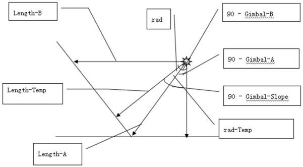
[0134] This embodiment is on the basis of embodiment 1, as image 3 As shown, in the step b3, the specific steps for obtaining the slope angle Slope by using the slope substitution module include:

[0135] b31. Drive the UAV to the area above the slope to be measured to ensure that the slope to be measured is within the viewing range;

[0136] b32. Adjust and fix the position of the gimbal, record the shooting distance Length-A of the calibration point A at the starting position of the slope, the pitch angle Gimbal-A of the exposure point, and the height H-A of the exposure point;

[0137] b33. Record the shooting distance Length-B of the calibration point B on the same level as the gimbal on the slope, the pitch angle Gimbal-B of the exposure point, and the height H-B of the exposure point;

[0138] b34. Obtain the included angle rad between the shooting distance Length-A of the calibration point A and the shooting distance Length-B of the calibration point B according to the ...


PUM


Abstract

The invention discloses an unmanned plane aerial photography image calibration method suitable for slope measurement. According to the method, firstly, an image calibration model is established; secondly, points are vertically acquired by an unmanned plane, slope map image data and calibration data are acquired, and a slope angle Slope and a slope image azimuth Azimuth are acquired through calculation according to the acquired data; whether a distance measurement module is available is determined, if yes, the distance measurement module is employed to measure the vertical distance Length; if not, calibration points are acquired to replace the vertical distance Length; according to the acquired vertical distance Length, a slope image scale SlopeScale, a geographic three-dimensional coordinate of an image origin Origin and a geographic three-dimensional coordinate of a target point are calculated, and calibration is accomplished. The method is advantaged in that the unmanned plane measurement calibration technology is made not to be limited to the plane, scientific basis is further provided for slope measurement and projection measurement demands, effective guarantee is provided foraccurate measurement, rapid and easy calibration is realized, and slope image calibration accuracy and calibration efficiency are improved.

Description

technical field [0001] The invention relates to the field of image calibration, in particular to a method for calibrating aerial images of drones suitable for slope measurement. Background technique [0002] Existing aerial calibration methods usually use UAV orthophoto measurement technology and oblique photography technology, among which: [0003] UAV orthophoto measurement technology is only used in flat areas. In hilly and hillside areas, due to the particularity of the landform, the accuracy of the measurement results decreases, and even only the projected area can be obtained. The final result is quite different from the actual data; [0004] The oblique photography technology can perform aerial calibration on the slope, which reorganizes the point cloud of multi-angle aerial pictures to obtain a 3D model for slope calibration and measurement; this method needs to collect a large number of multi-angle aerial pictures in the early stage, and through professional constru...

Claims


Application Information

Patent Timeline
Patent Type & Authority Patents(China)
IPC IPC(8): G06T7/80G01C25/00
CPCG01C25/00G06T7/85
Inventor 黄仁杰
Owner 成都准望科技有限公司
Why Eureka
Try Eureka