Continuous pin insertion machine for dipolar plug

A pin insertion machine and pin insertion technology, which is applied in the manufacture of contact box/base, contact manufacturing, etc., can solve the problems of inability to realize pin insertion operation, large error rate of pin placement, easy failure, etc., and achieve stable lifting , Improve the accuracy, improve the effect of accuracy

Active Publication Date: 2018-03-02
新沂市邵店众创工贸发展有限公司
View PDF4 Cites 2 Cited by
  • Summary
  • Abstract
  • Description
  • Claims
  • Application Information

AI Technical Summary

Problems solved by technology

[0003] Most of the existing needle insertion machines use manual needles and press needles through equipment, which is inefficient. In order to improve efficiency, most of the existing needle insertion machines use vibrating feeding trays to transport the needles, which need to be released by manipulators. This improves the work efficiency compared with manual needle insertion, but it still cannot achieve continuous needle insertion operation. There is a gap time for needle insertion in the middle, and there is a large error rate in needle insertion, which is prone to failure.

Method used


Image

  • Continuous pin insertion machine for dipolar plug
  • Continuous pin insertion machine for dipolar plug
  • Continuous pin insertion machine for dipolar plug

Examples


Embodiment Construction

[0037] In order to enable those skilled in the art to better understand the technical solutions of the present invention, the present invention will be described in detail below with reference to the accompanying drawings. The description in this section is only exemplary and explanatory and should not have any limitation on the scope of protection of the present invention. .

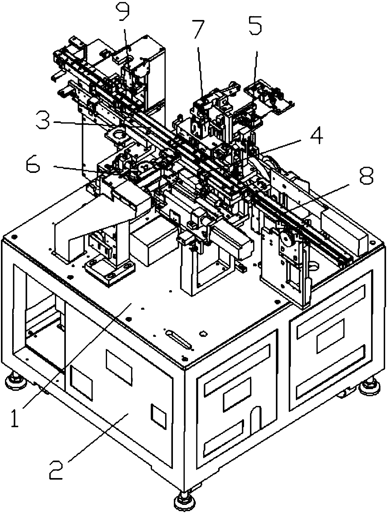
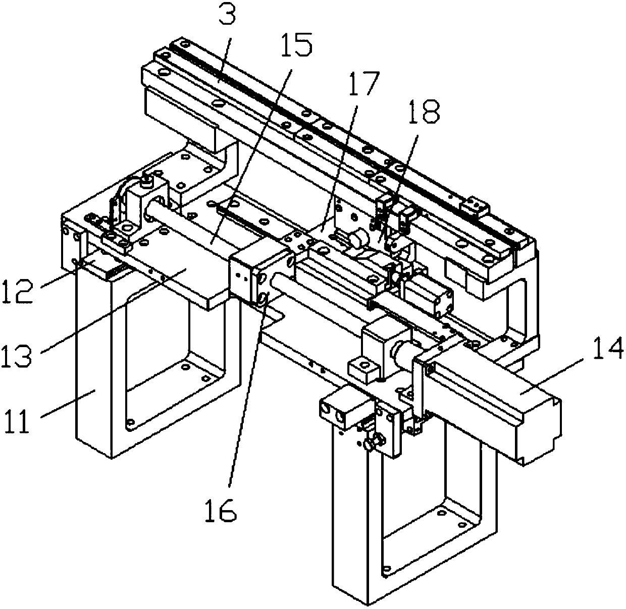
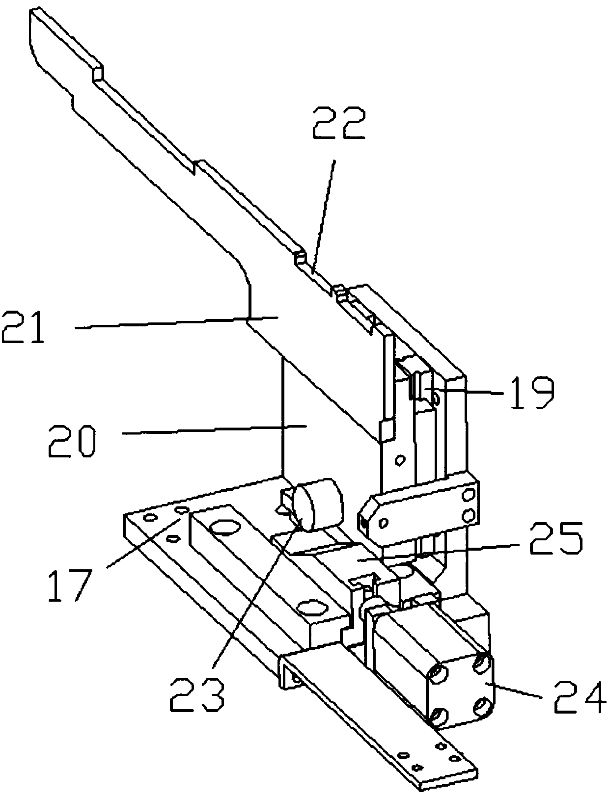
[0038] Such as Figure 1-Figure 10 As shown, the specific structure of the present invention is: a continuous pin machine for two-pole plugs, which includes a frame 1 and a power distribution control box 2, and the frame 1 is provided with a mutual matching and a material shell The matching feeding slot 3 and the feeding device 4 are provided above the feeding slot 3 with a matching pin mechanism 7 and a carrier tape needle feeding device 5, and the carrier tape needle feeding device 5 includes The carrier tape needle feeding seat 31 on the frame 1, the carrier tape needle feeding seat 31 is provided with...


PUM


Abstract

The invention relates to a continuous pin insertion machine for a dipolar plug. A frame is provided with a feeding groove and a feeding device, wherein an upper portion of the feeding groove is provided with a pin insertion mechanism and a carrier belt pin conveying device which are mutually matched, the carrier belt pin conveying device comprises a carrier belt pin conveying seat arranged on theframe, the carrier belt pin conveying seat is provided with a carrier belt pin conveying guiding cylinder and a carrier belt pin conveying groove, the carrier belt pin conveying groove is internally further provided with a carrier belt feeding sliding groove, the middle portion of the carrier belt pin conveying groove is matched with a carrier belt feeding ratchet, the carrier belt feeding ratchetis connected with a carrier belt feeding motor, the carrier belt pin conveying groove is provided with a pin insertion groove at an upper portion of the feeding groove, and the pin insertion groove is matched with a pin insertion block of the pin insertion mechanism. The continuous pin insertion machine is advantaged in that the carrier belt pin conveying device is employed to realize vertical conveying of carrier belts, vertical conveying of the insertion pins can be further realized, the carrier belt pin conveying device is matched with a material casing feeding device and the pin insertionmechanism, continuous pin insertion can be realized, work efficiency is improved, compared with a manipulator for pin insertion, the error rate is substantially reduced, and pin insertion accuracy isimproved.

Description

Technical field [0001] The invention relates to the field of pin insertion equipment, and in particular to a continuous pin insertion machine for two-pole plugs. Background technique [0002] A two-pole plug is a commonly used electrical component. Most of it includes a material shell that matches with each other. The material shell needs to be connected by a pin, so a pin machine is needed. [0003] Most of the existing pins are manually loaded, and the needle is pressed by equipment, which is inefficient. In order to improve efficiency, most of the existing pin-inserting machines use a vibrating feeder to transport the pins and need to be placed by a robot. Compared with manual needle placement, this improves work efficiency, but it still cannot achieve continuous needle insertion. There is a gap time between needle placement, and there is a large error rate in needle placement, which is prone to failure. Summary of the invention [0004] The purpose of the present invention is t...

Claims


Application Information

Patent Timeline
Patent Type & Authority Applications(China)
IPC IPC(8): H01R43/16H01R43/18
CPCH01R43/16H01R43/18
Inventor 邓君杨坤
Owner 新沂市邵店众创工贸发展有限公司
Why Eureka
Try Eureka