
Switch cabinet convenient for installing long bus

A switchgear and bus bar technology, applied in the field of switchgear, can solve the problems of troublesome expansion or maintenance, time-consuming and labor-intensive maintenance work, high assembly process requirements, etc., and achieve the effect of convenient and fast installation, smooth installation, convenient expansion and reduction

Pending Publication Date: 2018-03-02
HUZHOU ELECTRIC POWER COMPLETE EQUIP
View PDF5 Cites 2 Cited by
  • Summary
  • Abstract
  • Description
  • Claims
  • Application Information

AI Technical Summary

Problems solved by technology

[0002] Generally, the structure of the cabinet frame of the existing switchgear is generally made according to the specific required size. The connection methods of each structural piece are mainly non-detachable connection methods such as welding, or the disassembly end of the fastener connection is inside the cabinet body. After the production is completed, it is difficult to disassemble from the outside, especially the top. When performing maintenance or parts replacement, especially when the components on the top of the cabinet are damaged and need to be repaired or replaced, or components need to be added or removed for capacity expansion or reduction , from the inside of the cabinet, when various other components are covered with the switch cabinet, the maintenance work is time-consuming and laborious, and it is difficult to carry out, and the installation of the existing busbar is generally horizontally horizontal from the side after the busbar frame is completely installed. To be inserted into the socket, the designer needs to determine the length and quantity of the busbars and the layout method in advance, and the assembly process requirements are very high. The greater the distance between adjacent busbar frames, the more difficult the assembly will be; once the overall assembly of the power distribution cabinet is completed, it will be very troublesome when it needs to be expanded or repaired, and it is almost impossible

Method used


Image

  • Switch cabinet convenient for installing long bus
  • Switch cabinet convenient for installing long bus
  • Switch cabinet convenient for installing long bus

Examples


Embodiment

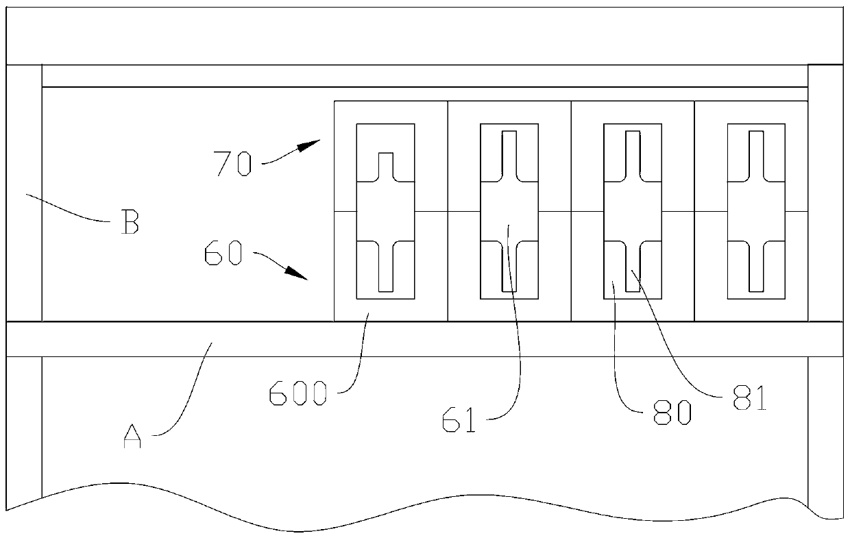
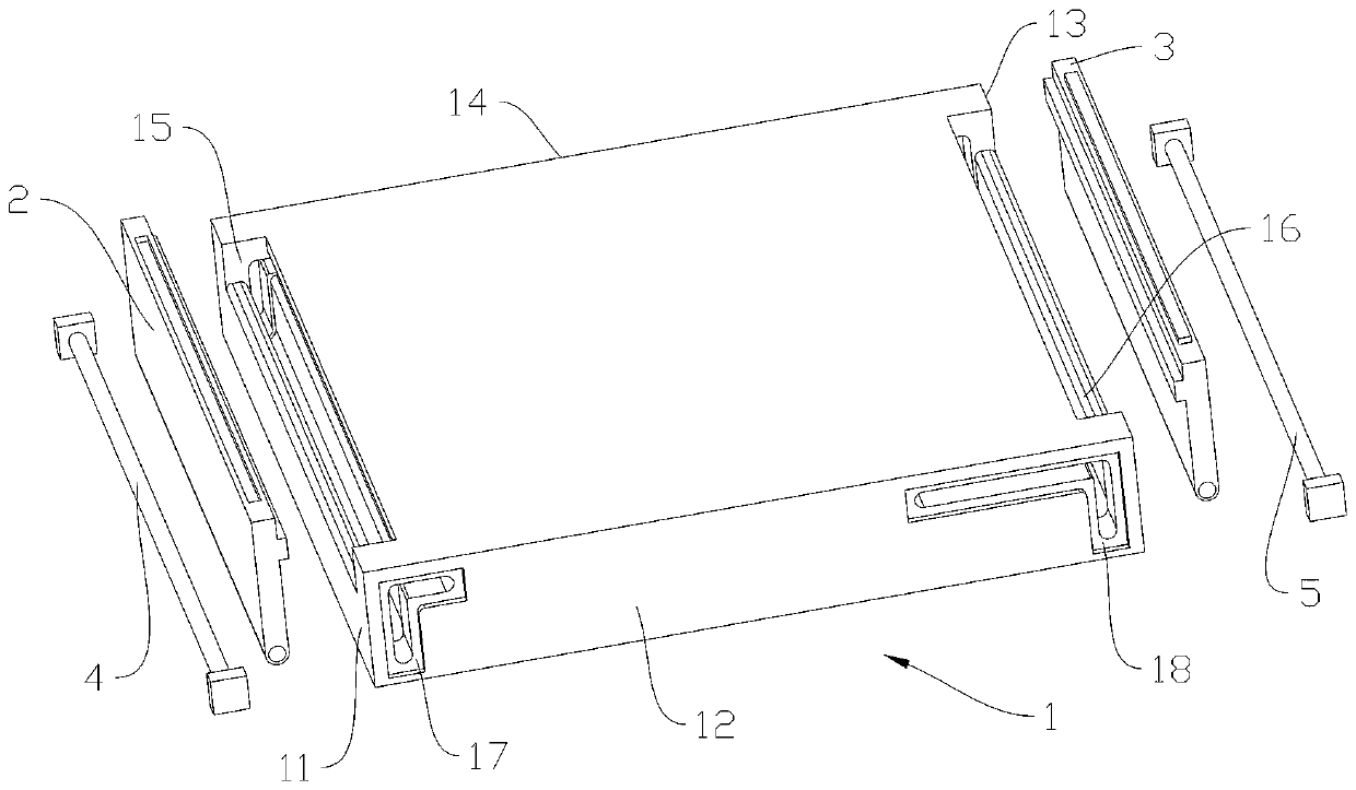
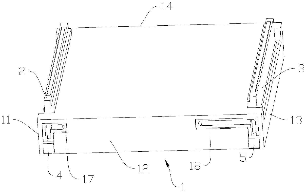
[0038] Example: such as Figure 1-8 As shown, a switchgear for easy installation of long busbars includes a switchgear body B, a detachable cabinet top on the switchgear body B, a busbar bridge A on the lower end of the cabinettop, and a busbar bridge A on the busbar The busbar frame; the cabinet top includes a plurality of cabinet top modules 100 that are slid into each other, and the cabinet top module 100 includes a cabinet top module body 1, and the cabinet top module body 1 has a first end 11, a second end 12, and a second end that are sequentially adjacent to each other. The three ends 13 and the fourth end 14 are characterized in that: the cabinet top module also includes a first slide insert 2 which can move in multiple directions at the first end 11 and a multi-directional movement at the third end 13. The moving second sliding insert 3 , the first control member 4 passing through between the second end 12 and the fourth end 14 and rotatably connected with the first s...


PUM


Abstract

The invention discloses a switch cabinet convenient for installing a long bus. The switch cabinet includes a switch cabinet body, a detachable cabinet top arranged on the switch cabinet body, a bus bridge arranged at the lower end of the cabinet top, and a bus frame erected on the bus bridge. The cabinet top includes multiple cabinet top modules inserted into one another in a sliding manner. The bus frame includes a bottom rack and a top rack which are jointed vertically. The bottom rack and the top rack are of the same structure, and are arranged in a mirroring manner. An appropriate number of cabinet top modules are selected and used according to the need to assemble or disassemble the switch cabinet, and the parts on the top of the switch cabinet are easy to maintain and replace. The bus frame is vertically installed, so that a bus can be put in the bottom rack in advance in the installation process of the bus frame, and the position of the bus can be controlled and adjusted freelyand conveniently. The number of the bus frame can be easily increased or decreased, and expansion and maintenance of the switch cabinet are facilitated.

Description

technical field [0001] The invention relates to the field of electric equipment, in particular to a switchgear for easy installation of long busbars. Background technique [0002] Generally, the structure of the cabinet frame of the existing switchgear is generally made according to the specific required size. The connection methods of each structural piece are mainly non-detachable connection methods such as welding, or the disassembly end of the fastener connection is inside the cabinet body. After the production is completed, it is difficult to disassemble from the outside, especially the top. When performing maintenance or parts replacement, especially when the components on the top of the cabinet are damaged and need to be repaired or replaced, or components need to be added or removed for capacity expansion or reduction , from the inside of the cabinet, when various other components are covered with the switch cabinet, the maintenance work is time-consuming and laborio...

Claims


Application Information

Patent Timeline
Patent Type & Authority Applications(China)
IPC IPC(8): H02B1/30H02G5/00
CPCH02B1/30H02G5/00
Inventor 丁玮
Owner HUZHOU ELECTRIC POWER COMPLETE EQUIP
Learn More