Noodle-cooking stove

A noodle-cooking stove and noodle-cooking technology, which is applied to cooking utensils with water bath devices, plug-ins, timing control ignition mechanisms, etc., can solve the problems of complex structure of noodle-cooking stoves, and achieve the effect of simplifying the structure and reducing the number of motors and components.

Active Publication Date: 2018-03-06
珠海优特智厨科技有限公司
View PDF5 Cites 7 Cited by
  • Summary
  • Abstract
  • Description
  • Claims
  • Application Information

AI Technical Summary

Problems solved by technology

[0003] The main purpose of the present invention is to provide a kind of cooking st

Method used


Image

  • Noodle-cooking stove
  • Noodle-cooking stove
  • Noodle-cooking stove

Examples


Embodiment 1

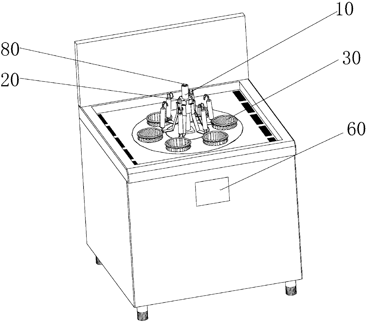
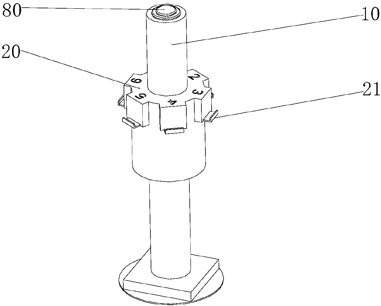
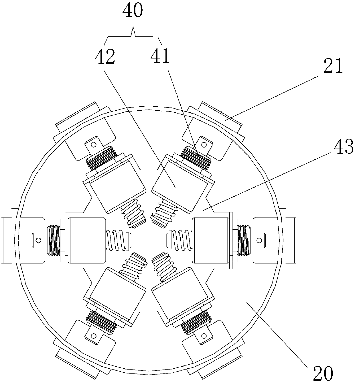
[0034] Such as figure 1 and figure 2 A noodle cooking stove shown includes a lifting rod 10; a hook assembly 20, the lifting rod 10 is provided with a hook assembly 20, the hook assembly 20 can move up and down following the lifting rod 10, and the hook assembly 20 includes a plurality of hooks 21, and each hook 21 can move relative to the lifting rod 10 and has a surface-taking state and a reset state; a surface frame 30, a plurality of surface frames 30, and the surface frame 30 can be hooked on the hook 21; make the hook 21 in the surface-taking The push-out device 40 that switches between the state and the reset state, when taking the face, the push-out device 40 pushes out the hook 21 to the direction away from the lift rod 10, so that the hook 21 is in the face-taking state to catch the face frame 30, and the lift rod 10 can be lifted to Drive the noodle frame 30 to lift; when cooking noodles, the push-out device 40 is separated from the hook 21, and the hook 21 is in ...

Embodiment 2

[0060] The difference from the first embodiment is that the hook 21 is reversed relative to the lifting rod 10 .

[0061] Optionally, when the hook 21 turns over relative to the lifting rod 10 , the top end of the hook 21 serves as a pivot end, and the bottom end of the hook 21 serves as a hook end to connect with the surface frame 30 .

[0062] Specifically, the top of the hook 21 is pivotally connected to the lifting rod 10, and the hook end of the hook 21 can be hooked on the surface frame 30. When the hook 21 switches to the surface-taking state, the pivot end of the hook 21 rotates, driving The articulated end moves away from the lifting rod 10, so that the articulated end can be hooked on the surface frame 30. When the hook 21 is switched to the reset state, the articulated end moves toward the direction close to the lifting rod 10, so as to achieve contact with the surface frame. 30's of separation.

[0063] From the above description, it can be seen that the above-men...


PUM


Abstract

The invention provides a noodle-cooking stove. The noodle-cooking stove comprises a lifting bar, a hook assembly, multiple noodle frames, a push-out device, and a control device, wherein the lifting bar is provided with the hook assembly, the hook assembly can move up and down along with the lifting bar, the hook assembly comprises multiple hooks, each hook can move relative to the lifting bar andhas a noodle getting state and a reset state, the multiple noodle frames can be suspended on the hooks, the push device enables the hook to switch between the noodle getting state and the reset state, when in the noodle getting state, the push device pushes the hook toward the direction far from the lifting bar, so that the hook is in the noodle getting state to hook the noodle frame, the liftingbar can lift up and down to drive the noodle frame to ascend and descend, when in boiling, the push device is separated from the hook, the hook is in the reset state, so as to separate the noodle frame from the hook, and the control device is connected with the lifting bar and the push device, so as to control the lifting bar to ascend and descend and the push device to act. The noodle-cooking stove overcomes the defect of complex structure of an existing noodle-cooking stove.

Description

technical field [0001] The invention relates to the technical field of electrical appliances, in particular to a noodle cooking stove. Background technique [0002] At present, the automatic lifting noodle frame electromagnetic noodle cooker on the market is that each noodle frame corresponds to a lifting rod. If the whole machine is equipped with six noodle frames, there will be six lifting rods, and there will be six motors for driving the lifting. They are all installed under the noodle cooker, so that the inner space of the noodle cooker with the heating electromagnetic coil and the movement is very narrow, and there are many driving parts at the same time, resulting in a larger volume of the noodle cooker, a complicated internal structure, and a circuit There are many control points and the internal wiring is messy, which makes the cost higher, the follow-up failure rate is high, and the maintenance cost increases. Contents of the invention [0003] The main purpose ...

Claims


Application Information

Patent Timeline
IPC IPC(8): A47J27/10A47J27/14A47J36/16A47J36/32A47J36/34
CPCA47J27/10A47J27/14A47J36/16A47J36/32A47J36/34
Inventor 姚晓宾李东星苏波张兵任玉成
Owner 珠海优特智厨科技有限公司
Why Eureka
Try Eureka