Industrial 3D simulation machine tool structure convenient to dismount and adjust

A machine tool and 3D technology, applied in the field of 3D simulation machine tools, can solve the problems of high transportation cost, inconvenient disassembly and transportation, and poor applicability of machine tools, and achieve the effects of simulating industrial production, improving practicability, and reducing transportation costs

Pending Publication Date: 2018-03-06
GUIZHOU UNIV
0 Cites 2 Cited by

AI-Extracted Technical Summary

Problems solved by technology

[0003] The purpose of the present invention is to provide an industrial 3D simulation machine tool structure that is easy to disassemble and adjust, so as to solve the problem that the existing simulation machine tools proposed in the above-mentioned background technology have poor app...

Abstract

The invention discloses an industrial 3D simulation machine tool structure that is easy to disassemble and adjust. A fixing groove is provided, and limit grooves are arranged on both sides of the fixing groove, threaded sockets are arranged on the surface of the mounting plate, fixed slide rails are arranged on both sides inside the machine tool body, and the load-bearing rod passes through the connecting slide The block is connected with the fixed slide rail, and the lifting sleeve is connected with the connecting plate through the supporting rod connected above. The industrial 3D simulation machine tool structure is easy to disassemble and adjust. There are two kinds of threaded sockets on the mounting plate, so that different processing machines can be installed on the mounting plate, so that in actual use, the machine tool can realize a variety of industrial production. Function, the machine tool body and the support rod can be disassembled and installed conveniently, which is conducive to disassembly and transportation and reduces transportation costs.

Application Domain

Large fixed members

Technology Topic

Threaded insertActual use +7

Image

  • Industrial 3D simulation machine tool structure convenient to dismount and adjust
  • Industrial 3D simulation machine tool structure convenient to dismount and adjust
  • Industrial 3D simulation machine tool structure convenient to dismount and adjust

Examples

  • Experimental program(1)

Example Embodiment

[0015] The technical solutions in the embodiments of the present invention will be clearly and completely described below with reference to the accompanying drawings in the embodiments of the present invention. Obviously, the described embodiments are only a part of the embodiments of the present invention, but not all of the embodiments. Based on the embodiments of the present invention, all other embodiments obtained by those of ordinary skill in the art without creative efforts shall fall within the protection scope of the present invention.
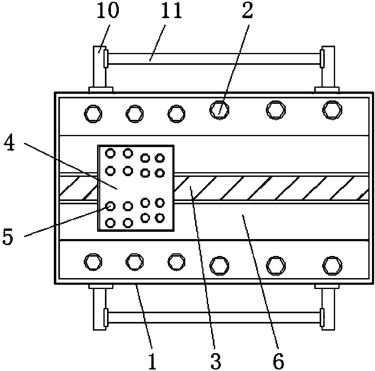
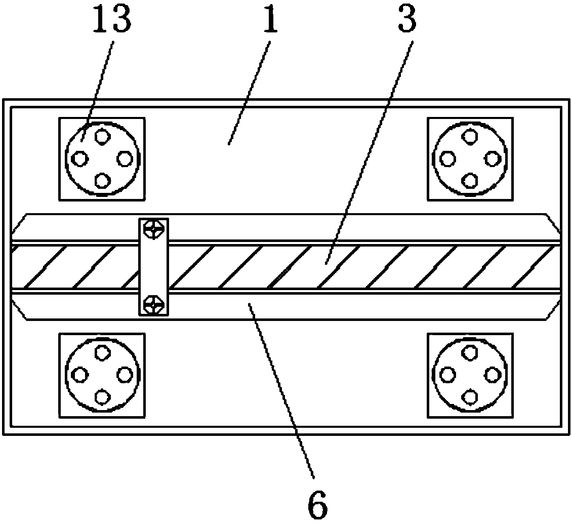
[0016] see Figure 1-3 , The present invention provides a technical solution: an industrial 3D simulation machine tool structure that is easy to disassemble and adjust, comprising a machine tool body 1, a fixing jack 2, a fixing groove 3, a mounting plate 4, a threaded jack 5, a limit groove 6, Connecting piece 7, fixing bolt 8, fixing slide rail 9, bearing rod 10, guide rail 11, connecting slide block 12, mounting plate 13, connecting plate 14, fixing screw 15, support rod 16 and lifting sleeve 17, on the machine body 1 There are fixing holes 2 on both sides of the surface. The fixing holes 2 are provided with two diameters on the upper surface of the machine body 1, and the radii of the three consecutive fixing holes 2 on the left side of the machine body 1 are smaller than the 3 consecutive fixing holes 2 on the right side. The radius of the jack 2 makes it easy to install suitable support plates according to different sizes of the fixed jack 2, which is convenient to complete the complete process of simulating industrial production, and the machine body 1 is provided with a fixed groove 3 inside, and the two sides of the fixed groove 3 are set The limiting groove 6 and the connecting piece 7 run through the fixing groove 3, and the lengths of the two are the same. At the same time, the two grooves are connected, so that the mounting plate 4 can move back and forth in the fixing groove 3 conveniently. The surface of the mounting plate 4 is provided with threads. The jack 5 and the screw jack 5 are provided with two diameters on the surface of the mounting plate 4, and the radius of the screw jack 5 on the left side of the center line of the mounting plate 4 is larger than the radius of the screw jack 5 on the right side of the center line of the mounting plate 4, The simulated mechanical equipment is installed according to the threaded socket 5 at a suitable distance. The mounting plate 4 is connected with the fixing bolt 8 through the lower connecting piece 7. The inside of the machine body 1 is provided with fixed slide rails 9 on both sides. The fixed slide rails 9 are about the fixed groove. The center line of 3 is symmetrically arranged with two groups, and the fixed slide rail 9 is movably connected with the connecting slider 12, so that the guide rail 11 can be easily pulled out or stored from the inside of the machine body 1, and the load-bearing rod 10 is connected with the fixed slide rail through the connecting slider 12. 9 is connected, and a guide rail 11 is installed on the inner side of the bearing rod 10, a mounting plate 13 is fixed under the machine body 1, and the mounting plate 13 is connected with the connecting plate 14 through the lower fixing screw 15, and the lifting sleeve 17 is connected through the upper part. The supporting rod 16 is connected with the connecting plate 14, the supporting rod 16 and the lifting sleeve 17 constitute a telescopic structure, and the supporting rod 16 and the connecting plate 14 are welded integrated structure, which is convenient to change the overall height, and the welding method makes the overall Higher stability.
[0017] Working principle: First, according to the installed simulated mechanical equipment, move the mounting plate 4 to the appropriate position in the limit groove 6, at this time the connecting piece 7 moves in the fixing groove 3, and then operate the fixing bolt 8 to the connecting piece 7. Fasten it, then install the simulation machine on the mounting plate 4, select the appropriate threaded socket 5 according to the size of the simulation machine for installation, and then use the fixed socket 2 to install the supporting platform required for industrial processing. When it is necessary to use the guide rail At 11:00, the load-bearing rod 10 can be pulled out from the inside of the machine body 1, that is, the load-bearing rod 10 is moved in the fixed slide rail 9 by connecting the slider 12. The design of the guide rail 11 provides a moving slide rail for the simulation processing machine, which is convenient for The industrial production simulation is carried out, and when the guide rail 11 is not needed, it is accommodated inside the machine body 1, which is convenient to reduce the overall volume. When the overall height needs to be adjusted, the support rod 16 is removed from the lifting sleeve 17. It can be pulled out. After the industrial simulation is completed, the fixing screw 15 is disassembled, and the mounting plate 13 and the connecting plate 14 are separated, which is convenient for separate packaging and transportation, and saves transportation costs. The above design increases the overall practicability.
[0018] Although embodiments of the present invention have been shown and described, it will be understood by those skilled in the art that various changes, modifications, and substitutions can be made in these embodiments without departing from the principle and spirit of the invention and modifications, the scope of the present invention is defined by the appended claims and their equivalents.

PUM

no PUM

Description & Claims & Application Information

We can also present the details of the Description, Claims and Application information to help users get a comprehensive understanding of the technical details of the patent, such as background art, summary of invention, brief description of drawings, description of embodiments, and other original content. On the other hand, users can also determine the specific scope of protection of the technology through the list of claims; as well as understand the changes in the life cycle of the technology with the presentation of the patent timeline. Login to view more.

Similar technology patents

Organochlorine pesticide polluted site soil remediation pretreatment device and method

Owner:NANJING INST OF ENVIRONMENTAL SCI MINIST OF ECOLOGY & ENVIRONMENT OF THE PEOPLES REPUBLIC OF CHINA

Preparation method of nisin aqueous solution with high clarity and high potency

InactiveCN107286226AHigh potencyreduce shipping costs
Owner:ZHEJIANG SILVER ELEPHANT BIO ENG

Carpool route optimization method and device, storage medium, and computing device

ActiveCN109102123Areduce shipping costsGuarantee the quality of logistics services
Owner:ANJI AUTOMOTIVE LOGISTICS +1

Classification and recommendation of technical efficacy words

  • Improve practicality
  • reduce shipping costs

Device and method for constructing self-adaptive graphic user interface (GUI)

ActiveCN102193786ASolve control intersection and information truncation problemsImprove practicality
Owner:INDUSTRIAL AND COMMERCIAL BANK OF CHINA

Photographing method and terminal

Owner:GUANGDONG OPPO MOBILE TELECOMM CORP LTD

Preparation method of polyester type pure solid polycarboxylic acid high-performance water reducing agent

ActiveCN103012694Areduce shipping costsMarket competitiveness and application prospects are good
Owner:BEIJING UNIV OF TECH

Method for preparing modified biochar with aquatic plant waste and hematite

InactiveCN105771898Alow costreduce shipping costs
Owner:LIAONING UNIVERSITY OF PETROLEUM AND CHEMICAL TECHNOLOGY
Why Eureka
Try Eureka