Stator punching sheet storage and transportation device

A transportation device and stator punching technology, which is applied in the field of mechanical processing, can solve the problems of confusion on site, inability to be used universally, and low utilization rate of tooling, and achieve the effects of high degree of generalization, convenient access and low manufacturing cost.

Inactive Publication Date: 2018-03-06
刘晓东
View PDF0 Cites 2 Cited by
  • Summary
  • Abstract
  • Description
  • Claims
  • Application Information

AI Technical Summary

Problems solved by technology

[0002] The traditional storage of stator punching generally uses shelves, columns and chassis, and the stator punching is placed on the shelf. Generally, a shelf can only store one kind of stator punching, which cannot be used universally. The utilization rate of tooling is low. When the production task is heavy, one side The empty frame is idle, and the stator punching is stored on the ground on one side, causing confusion on site. Therefore, a stator punching storage and transportation device with general functions and convenient operation is required.

Method used


Image

  • Stator punching sheet storage and transportation device
  • Stator punching sheet storage and transportation device
  • Stator punching sheet storage and transportation device

Examples


Embodiment 1

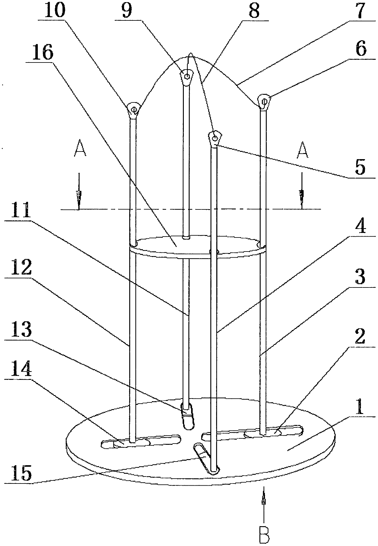
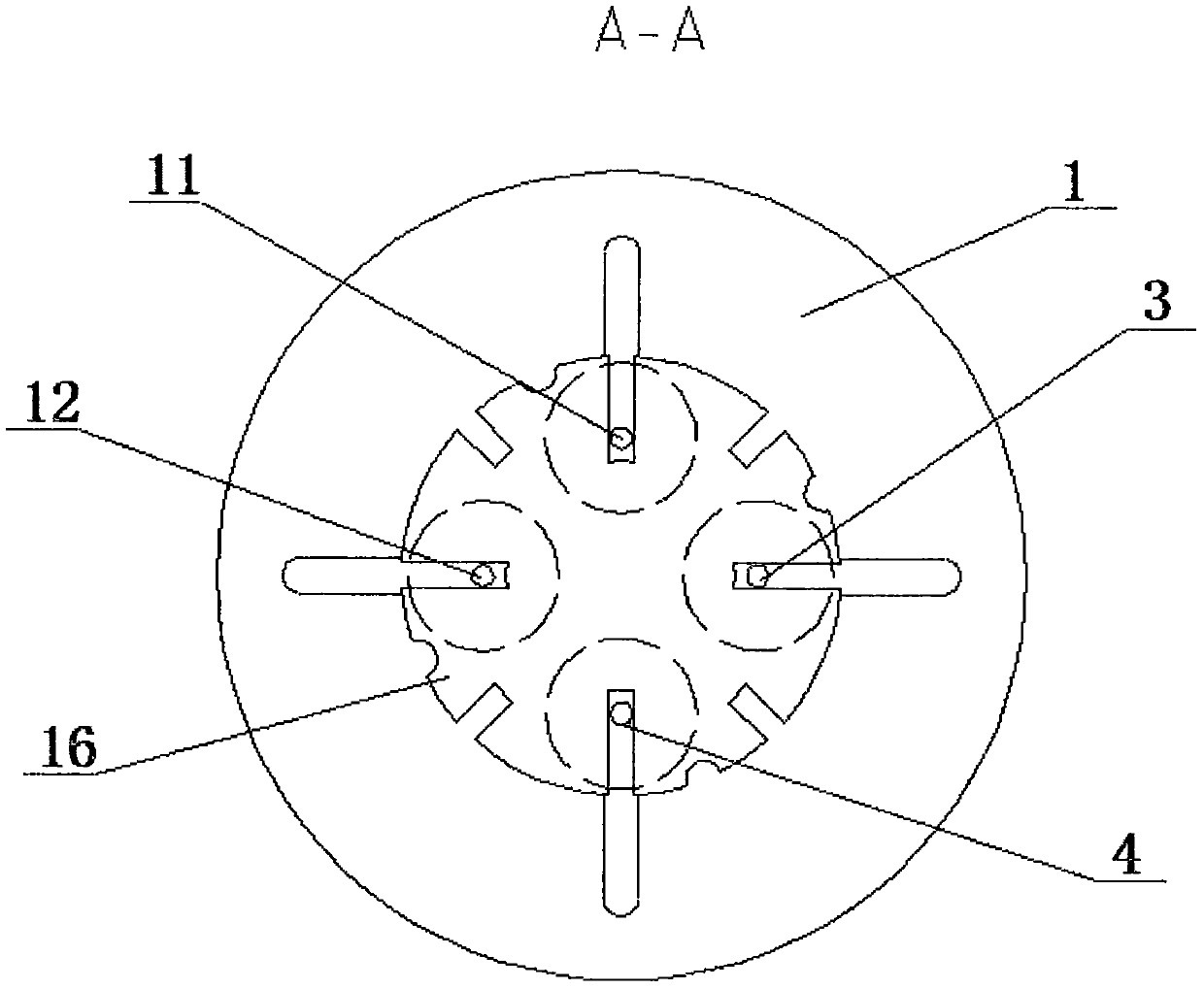
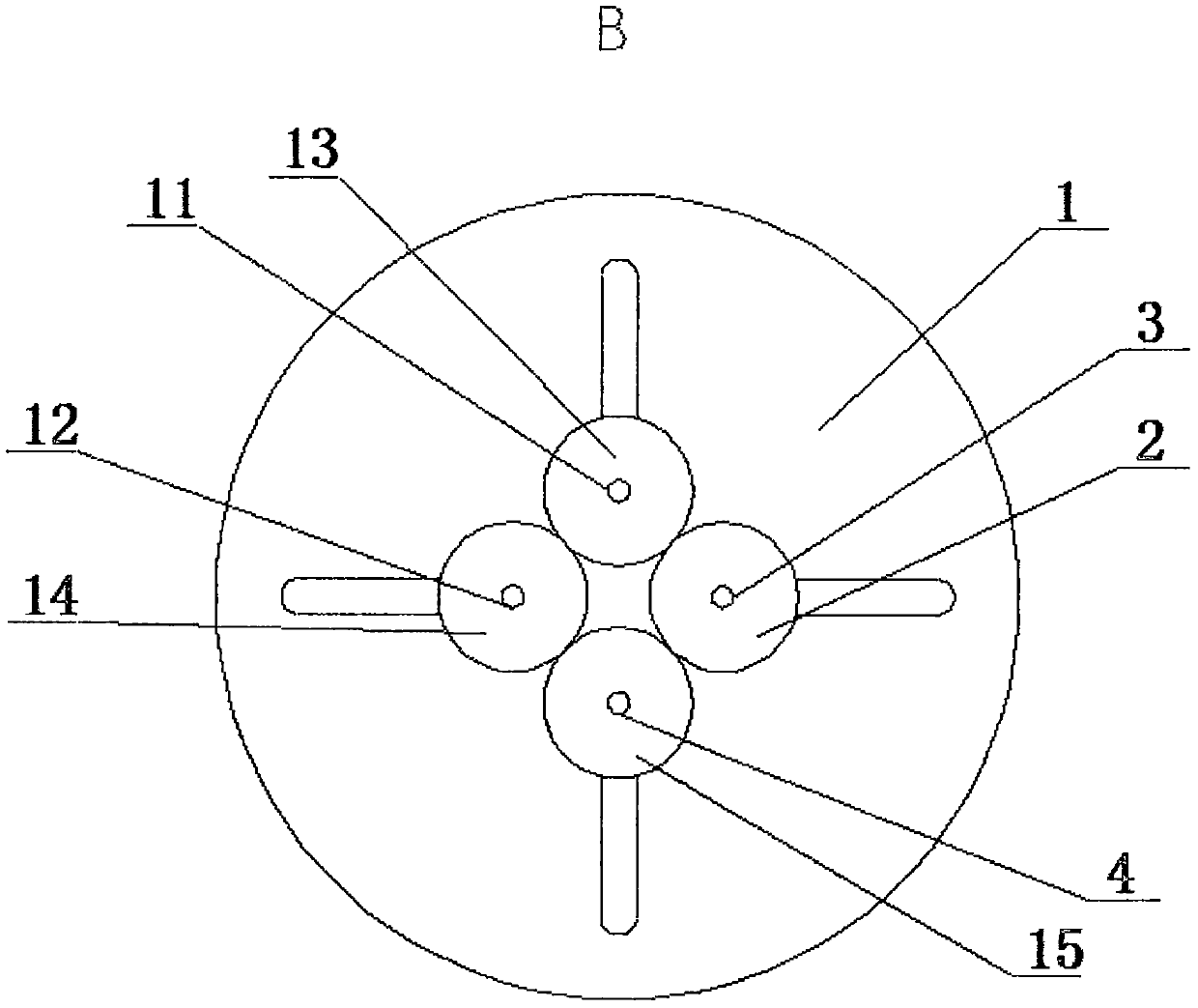
[0021] Such as figure 1 , figure 2 , image 3 and Figure 4 As shown, a stator punch storage and transportation device includes a chassis 1 and a chuck 16. The chassis 1 is a circular thin-walled part, and the chassis 1 is provided with 4 oblong holes. The 4 The four oblong holes are arranged in a cross shape, the symmetrical center of the four oblong holes is the center of the chassis 1, and the oblong holes are sequentially provided with column A3, column C11, column D12 and column B4 in the counterclockwise direction. The head of the column A3 is provided with a hook A6, the bottom surface of the column A3 is provided with a disk A2, the head of the column B4 is provided with a hook B5, and the bottom surface of the column B4 is provided with a disk B15. The head of the column C11 is provided with a hook C9, the bottom surface of the column C11 is provided with a disk C13, the head of the column D12 is provided with a hook D10, and the bottom surface of the column D12 i...

Embodiment 2

[0029] Such as figure 1 , figure 2 , image 3 , Figure 4 and Figure 5 As shown, a stator punch storage and transportation device includes a chassis 1, a chuck 16 and a chuck 20, the chassis 1 is a circular thin-walled part, and the chassis 1 is provided with 4 oblong holes, The four oblong holes are arranged in a cross shape, the symmetrical center of the four oblong holes is the center of the chassis 1, and the oblong holes are sequentially arranged with column A3, column C11, column D12 and column B4 in the counterclockwise direction , the head of the column A3 is provided with a hook A6, the bottom surface of the column A3 is provided with a disc A2, the head of the column B4 is provided with a hook B5, and the bottom surface of the column B4 is provided with a disc B15 , the head of the column C11 is provided with a hook C9, the bottom surface of the column C11 is provided with a disc C13, the head of the column D12 is provided with a hook D10, and the bottom surfac...


PUM


Abstract

The invention relates to a storage and transportation device for stator punching, which includes a chassis and a chuck. The chassis is provided with 4 oblong holes, which are arranged in a cross shape. Column A, column B, and column C pass through the four oblong holes. and column D, the bottom surfaces of column A, column B, column C and column D are respectively provided with the heads of disc A, disc B, disc C and disc D, column A, column B, column C and column D Hook A, hook B, hook C and hook D are set respectively, hook A and hook D are connected by sling A, hook B and hook C are connected by sling B, and the diameter of the disc is larger than the width of the oblong hole , the diameter of column A, column B, column C and column D is smaller than the width of the oblong hole, and the edge of the chuck is evenly provided with 4 bar-shaped grooves A, 4 bar-shaped grooves B and gaps; the present invention has the advantages of convenient access, storage The utility model has the advantages of various types, convenient adjustment, simple structure and low cost.

Description

technical field [0001] The invention belongs to the field of mechanical processing, and in particular relates to a storage and transportation device for stator punching pieces. Background technique [0002] The traditional storage of stator punching generally uses shelves, columns and chassis, and the stator punching is placed on the shelf. Generally, a shelf can only store one kind of stator punching, which cannot be used universally. The utilization rate of tooling is low. When the production task is heavy, one side The empty frame is idle, and the stator punching is stored on the floor on one side, causing confusion on site. Therefore, a stator punching storage and transportation device with general functions and convenient operation is needed. Contents of the invention [0003] The object of the present invention is to overcome the deficiencies of the prior art, and provide a storage and transportation device for stator punching pieces with convenient access, various s...

Claims


Application Information

Patent Timeline
Patent Type & Authority Applications(China)
IPC IPC(8): B65D21/08B65D6/08
CPCB65D21/086B65D7/14
Inventor 刘晓东
Owner 刘晓东
Why Eureka
Try Eureka