
Scope pollution control system and method used for separate system drainage pipe network system

A drainage pipe network and pollution control technology, applied in waterway systems, sewage removal, drainage structures, etc., can solve the problems that surface pollution cannot be effectively intercepted and treated, and sewage and rainwater cannot be accurately controlled.

Pending Publication Date: 2018-03-06
WUHAN SHENGYU DRAINING SYST
View PDF8 Cites 0 Cited by
  • Summary
  • Abstract
  • Description
  • Claims
  • Application Information

AI Technical Summary

Problems solved by technology

[0010] Aiming at the defects in the above-mentioned prior art, the purpose of the present invention is to solve the above-mentioned deficiencies in the background technology, and provide a surface pollution control method for the diversion system drainage pipe network system, which solves the problems of urban unit areas and pollution in the prior art. The technical problems that surface pollution of municipal road areas cannot be effectively intercepted and treated, and sewage and rainwater cannot be accurately controlled

Method used


Image

  • Scope pollution control system and method used for separate system drainage pipe network system
  • Scope pollution control system and method used for separate system drainage pipe network system
  • Scope pollution control system and method used for separate system drainage pipe network system

Examples


Embodiment 1

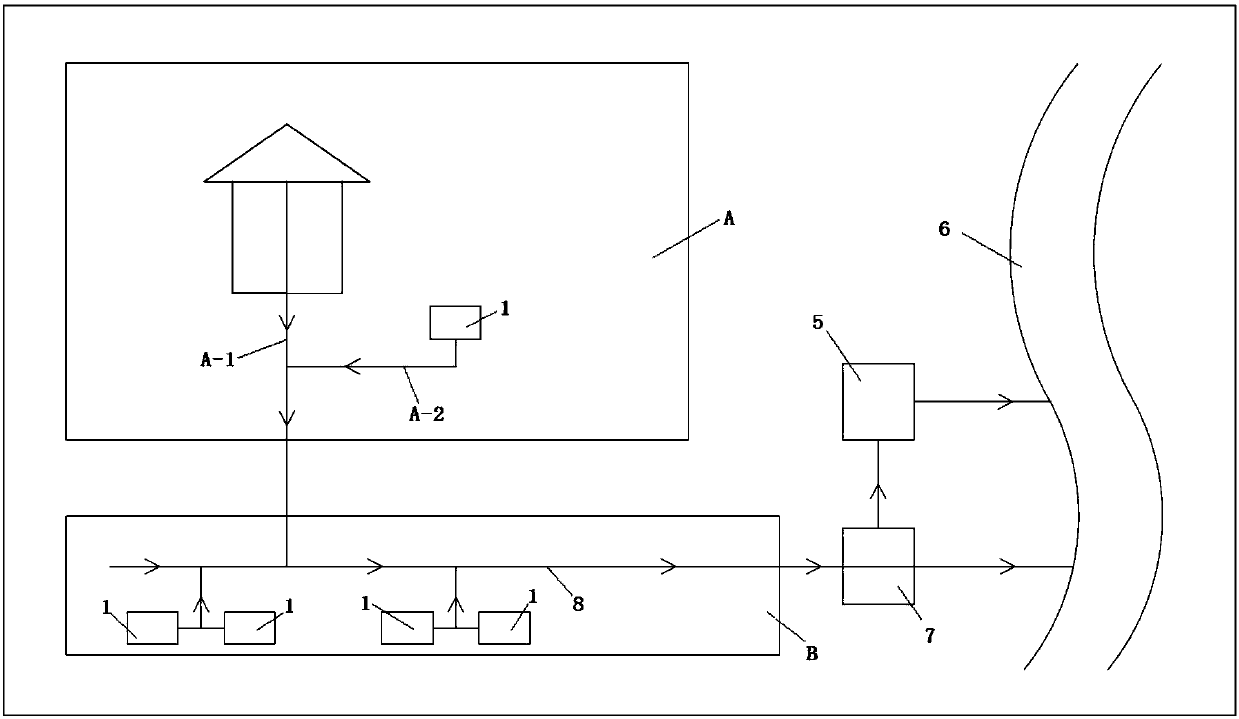
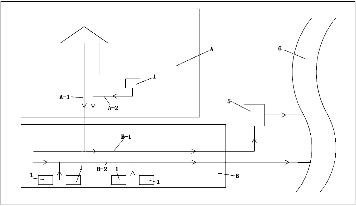
[0114] Such as Figure 4 As shown, the first primary rain storage tank C is arranged between the sewage pipeline A-1 and the rainwater pipeline A-2, and the water inlet end of the first primary rain storage tank C is connected with the rainwater pipeline A-2. The drainage end of the rain storage tank C is connected to the sewage pipeline A-1, and the rainwater pipeline A-2 is provided with a bottom-opening weir gate 9, and the water inlet end of the bottom-opening weir gate 9 is located in the first primary rain storage tank C Downstream of the water inlet end; the second primary rain storage tank D is set between the sewage main pipe B-1 and the rainwater main pipe B-2; the water inlet end of the second primary rain storage tank D is connected to the rainwater main pipe B -2 is connected, the drainage end of the second primary rain storage tank D is connected with the sewage main pipe B-1; the rainwater main pipe B-2 is provided with a bottom-opening weir gate 9, and the wate...

Embodiment 2

[0116] Such as Figure 5 As shown, the rainwater pipeline A-2 is connected with a rainwater pretreatment system through a branch pipe, and the branch pipe is provided with a bottom opening weir gate 9, and the bottom opening weir gate 9 is located at the upstream of the rainwater pretreatment system; the rainwater main pipe B-2 The upper part is connected with a rainwater pretreatment system through a branch pipe, and the branch pipe is provided with a bottom opening weir gate 9, which is located upstream of the rainwater pretreatment system.

Embodiment 3

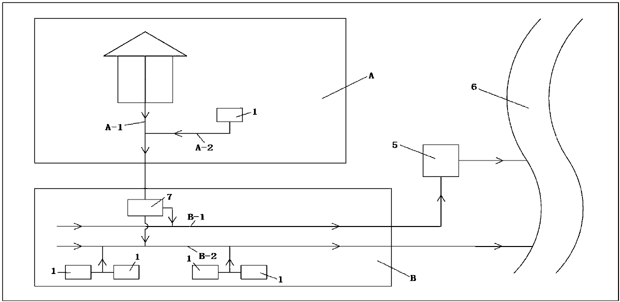
[0118] Such as Image 6 As shown, the first primary rain storage tank C is arranged between the sewage pipeline A-1 and the rainwater pipeline A-2, and the water inlet end of the first primary rain storage tank C is connected with the rainwater pipeline A-2. The drainage end of the rain storage tank C is connected to the sewage pipeline A-1, and the rainwater pipeline A-2 is provided with a bottom-opening weir gate 9, and the water inlet end of the bottom-opening weir gate 9 is located in the first primary rain storage tank C Downstream of the water inlet end; the rainwater main pipe B-2 is connected with a rainwater pretreatment system through a branch pipe, and the branch pipe is provided with a bottom opening weir gate 9, which is located upstream of the rainwater pretreatment system.


PUM


Abstract

The invention discloses a scope pollution control system and method used for a separate system drainage pipe network system. The scope pollution control system comprises a sewage dry pipe and a rainwater dry pipe; a sewage treatment plant is arranged at an outlet of the sewage dry pipe; an outlet of the rainwater dry pipe is communicated with a natural water body, a second rainwater treatment system is arranged on the rainwater dry pipe, the water inlet end of the rainwater treatment system is communicated with the rainwater dry pipe, and the drainage end of the rainwater treatment system is communicated with the sewage dry pipe. The scope pollution control system is simple in structure and convenient to build, sewage and initial rainwater in all areas which are divided according to administrative functions in a city can be efficiently treated simply by building an initial rain storage pond in a limited area of a municipal administration road.

Description

technical field [0001] The invention relates to a surface pollution control method, which belongs to the technical field of decentralized source surface pollution control, and in particular to a surface pollution control system and method for a diversion system drainage pipe network system. Background technique [0002] Urban municipal drainage systems are mainly divided into combined drainage systems and divergent drainage systems. The first combined drainage system that appeared was to mix domestic sewage, industrial wastewater and rainwater in the same pipe, and directly discharge it into the nearby water body without any treatment, which seriously polluted the receiving water body. Many old cities at home and abroad almost All in this way. The interception combined drainage system is often used now. [0003] The structure of the intercepting combined drainage system is basically the same as that of the traditional combined drainage system. The difference is that the in...

Claims


Application Information

Patent Timeline
Patent Type & Authority Applications(China)
IPC IPC(8): E03F1/00E03F5/04E03F5/10E03F5/14
CPCE03F1/00E03F5/0401E03F5/041E03F5/10E03F5/14Y02A10/30
Inventor 周超李习洪
Owner WUHAN SHENGYU DRAINING SYST
Learn More