Piston compressor safety protection device

A technology for a safety protection device and a compressor, applied in the field of compressors, can solve problems such as failure to prevent damage to the compressor, and achieve the effects of avoiding equipment loss, having a practical and reliable structure

Pending Publication Date: 2018-03-06
成都市博磊化工机械有限公司
View PDF4 Cites 0 Cited by
  • Summary
  • Abstract
  • Description
  • Claims
  • Application Information

AI Technical Summary

Problems solved by technology

Practice has proved that during manual shutdown, it usually takes at least a few minutes from judging the fault to identifying the fault and then to emergency shutdown, so it is almost impossible to prevent the compressor from being damaged.

Method used


Image

  • Piston compressor safety protection device
  • Piston compressor safety protection device
  • Piston compressor safety protection device

Examples


Embodiment 1

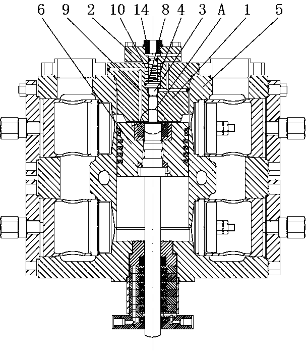
[0034] Such as Figures 1 to 5 As shown, a safety protection device for a piston compressor includes an installation body 1, a press-fit body 2, a contact push rod 3, an elastic element 4 and a trigger mechanism (not shown in the figure);

[0035]The installation body 1 is sealed and fixedly installed on the compressor body 5 at the position facing the end of the piston cylinder, and extends into the piston cylinder. The installation body 1 is provided with a step hole 7, and the push rod 3 has a step portion 8. The touch push rod 3 is installed in the step hole 7, and the outer opening of the step hole 7 is sealed and fixedly installed with the press-fit body 2, and the press-fit body 2 is provided with a through hole corresponding to the outer end of the touch push rod 3, and the outside The end is located in the through hole, and the trigger mechanism is installed directly above the outer end surface of the push rod 3. The trigger mechanism is connected to the automatic shu...

Embodiment 2

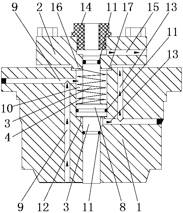
[0041] Such as Figures 1 to 5 As shown, on the basis of Embodiment 1, a pressure relief groove is provided on the inner wall of the step hole 7, and a pressure relief chamber 12 is formed between the pressure relief groove and the outer wall of the contact push rod 3, and the pressure relief groove is located between the step portion 8 and the mounting body. Between the inner end faces of 1, a first pressure relief hole 13 is opened on the installation body 1, and the first pressure relief hole 13 communicates the pressure relief chamber 12 with the outside world, so that the medium leaking through the piston cylinder and the closed cavity 10 leak out The medium in the pressure relief chamber 12 can be discharged to the atmosphere through the first pressure relief hole 13 to prevent the pressure in the pressure relief chamber 12 from being too high, which will cause the pressure of the medium in the pressure relief chamber 12 to cause excessive force on the step portion 8 in t...

Embodiment 3

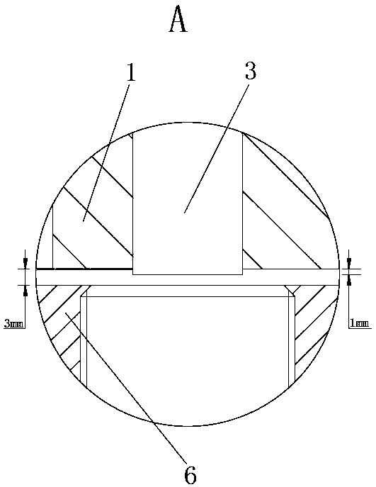
[0044] Such as Figures 6 to 11 As shown, on the basis of Embodiment 2, two sets of safety protection devices are installed on the piston compressor body 5. At the same time, different from Embodiments 1 and 2, these two sets of safety protection devices are specifically installed on the horizontal piston On the type compressor, two sets of safety protection devices are installed on the body 5 through the hollow cylinder head 18, and the touch and push rods 3 of the two sets of safety protection devices are symmetrical with respect to the center line of the piston cylinder, and the respective touch and push rods of the two sets of protection devices The difference between the inner end surface of the rod 3 and the inner end surface of the corresponding installation body 1 is 0.5mm, and the safety protection device with a larger distance between the inner end surface of the push rod 3 and the inner end surface of the installation body 1 The trigger mechanism is connected to the...


PUM


Abstract

The invention relates to the technical field of compressors, and discloses a piston compressor safety protection device. The piston compressor safety protection device comprises a mounting body mounted on a machine body and provided with a step hole; a touch push rod, provided with a step part, is mounted in the step hole; an outer side aperture of the step hole is fixedly connected with a pressing body; the pressing body is provided with a through hole; the outer side end part of the touch push rod is in the through hole; a trigger mechanism is mounted rightly above the end part of the touchpush rod; an elastic element is arranged between the pressing body and the step part; the inner side end part of the touch push rod penetrates outside from the step hole, and exceeds the inner end surface of the mounting body by a section of distance, and the distance is smaller than a piston stop point gap value; the mounting body is provided with a pressure balance hole; a closed cavity surrounded by the pressing body, the step part, the touch push rod and the inner wall of the step hole communicates with a piston cylinder; and the area of the inner side end surface of the touch push rod issmaller than the contact area of a compression medium in the closed cavity with one end surface of the step part. When a piston compressor is badly broken down, automatic and quick stop can be realized, so that the compressor can be stopped before damage of a compressor body to prevent the equipment loss.

Description

technical field [0001] The invention relates to the technical field of compressors, in particular to a safety protection device for a piston compressor. Background technique [0002] As a general-purpose machine, piston compressors are widely used in many industries such as petroleum, chemical industry, electric power, construction engineering, mining, steel, metallurgy, automobiles, chemical fibers, pharmaceuticals, food, etc. How to ensure the safe operation of compressors has always been important topics to explore. [0003] Due to the high failure rate of piston compressors, and some failures will lead to major accidents. Therefore, general compressors are equipped with common safety protection devices. For example, the non-continuously operating air compressors used in construction and mining industries will automatically stop when the pressure of the air storage tank reaches the set value to avoid overloading and protect their safety. Another example is the compress...

Claims


Application Information

Patent Timeline
Patent Type & Authority Applications(China)
IPC IPC(8): F04B49/10F04B39/00
Inventor 张正勇潘仲高
Owner 成都市博磊化工机械有限公司
Why Eureka
Try Eureka