Gear interlocking device for automobile transmission

A technology of automobile transmission and interlocking device, which is used in transmission control, components with teeth, belt/chain/gear, etc., can solve the problem of damage to the internal gear of the transmission, the length of the spring should not be too long, the interlocking device is not sensitive, etc. problems, to achieve the effect of less space, long life of the interlocking device, and compact structure

Active Publication Date: 2018-03-06
LIXIN COUNTY YURUO INFORMATION TECH CO LTD
View PDF3 Cites 0 Cited by
  • Summary
  • Abstract
  • Description
  • Claims
  • Application Information

AI Technical Summary

Problems solved by technology

[0005] (1) The commonly used interlocking device is provided with a slidable slider or a steel ball between two shift fork shafts, and a slot for accommodating the slider or steel ball is correspondingly provided on the shift fork shaft. When the shafts are in the neutral position, the slider or the steel ball can move freely, but the elasticity of the spring will decrease or even lose its elasticity after long-term use, which will cause the interlock device to be insensitive and damage the internal gear of the transmission, the slider or the baffle type The volume of the interlocking device is relatively large, occupying a large space in the car
[0006] (2) The length of the existing gear interlocking device cannot be too long because of the spring, otherwise the elasticity will be lost, so the distance between two adjacent shift fork shafts is very small, the processing is relatively fine, the processing requirements are high, and the cost is high

Method used


Image

  • Gear interlocking device for automobile transmission
  • Gear interlocking device for automobile transmission
  • Gear interlocking device for automobile transmission

Examples


Embodiment

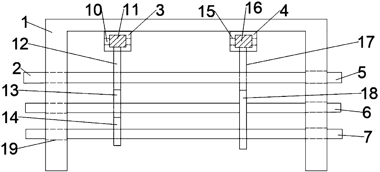
[0026] Such as figure 1 As shown, the present invention provides a gear interlocking device for an automobile transmission, including a mounting base 1, which is fixedly installed in the mounting frame at the bottom of the automobile, and a shift fork shaft 2 is installed on the side of the mounting base 1, The shift fork shaft 2 is also called the gear shift shaft. A shift fork is installed on the outside of the shift fork shaft 2. The shift fork shaft 2 moves axially so that the shift fork is connected to a certain gear so that the car can shift gears. The section of the end of the mounting seat 1 The shape is U-shaped, and the U-shaped mounting seat 1 saves space, and is more convenient to install the shift fork shaft 2. The side of the mounting seat 1 is provided with a mounting hole 19, and the shift fork shaft 2 is inserted in the mounting hole 9. The shift fork shaft 2 slides left and right in the installation hole 19, and the installation hole 19 restricts the shift fo...


PUM


Abstract

The invention discloses a gear interlocking device for an automobile transmission. The gear interlocking device comprises an installing seat. Shifting fork shafts are installed on the side face of theinstalling seat, a first shaft seat and a second shaft seat are fixedly installed on the bottom face of the installing seat, the shifting fork shafts comprise the first shifting fork shaft, the second shifting fork shaft and the third shifting fork shaft, and first grooves are formed in the outer sides of the left ends of the first shifting fork shaft, the second shifting fork shaft and the thirdshifting fork shaft correspondingly; second grooves are formed in the outer sides of the right ends of the first shifting fork shaft and the third shifting fork shaft correspondingly, the first shaftseat is provided with a left shaft sleeve through a left fixing shaft, and a first clamping rod, a second clamping rod and a third clamping rod are fixedly installed on the outer side of the left shaft sleeve; and the second shaft seat is provided with a right shaft sleeve through a right fixing shaft, and a first limiting rod and a third limiting rod are installed on the outer side of the rightshaft sleeve. According to the gear interlocking device, the structure is simple, less space is occupied, the structure is compact, the service life of the interlocking device is long, and an automobile can travel more stably; and the axial movement of the shifting fork shafts is stable, the interlocking effect of the interlocking device is good, the machining requirement is low, and the cost is low.

Description

technical field [0001] The invention relates to the technical field of automobile transmission devices, in particular to a gear interlock device for automobile transmissions. Background technique [0002] In order to output the torque and speed suitable for each working condition to the driving wheels of the car, it is necessary to shift gears. Selecting different gears will output different speeds and torques to the driving wheels. If the car transmission selects two or more gears at the same time gear, then the internal gears of the transmission may be stuck or even damaged. The function of the interlock device is to prevent the transmission from being engaged in two or more gears at the same time. At present, most interlock mechanisms have separate parts such as interlock plates and interlock pins. These parts are added to the shift mechanism. This increases the complexity of the structure and takes up valuable space in the transmission. [0003] In recent years, people...

Claims


Application Information

Patent Timeline
Patent Type & Authority Applications(China)
IPC IPC(8): F16H63/36
CPCF16H63/3408F16H63/36
Inventor 刘杰
Owner LIXIN COUNTY YURUO INFORMATION TECH CO LTD
Why Eureka
Try Eureka