
Converter and control method thereof

A converter and control signal technology, applied in control/regulation systems, instruments, converting DC power input to DC power output, etc., can solve problems such as increasing the difficulty of control loop design

Inactive Publication Date: 2018-03-06
UNITED AUTOMOTIVE ELECTRONICS SYST
View PDF3 Cites 2 Cited by
  • Summary
  • Abstract
  • Description
  • Claims
  • Application Information

AI Technical Summary

Problems solved by technology

Furthermore, when the lower tube is closed, the transfer function of the system control to the output has changed greatly, which increases the difficulty of the design of the control loop

Method used


Image

  • Converter and control method thereof
  • Converter and control method thereof
  • Converter and control method thereof

Examples


Embodiment Construction

[0045] The specific implementation manner of the present invention will be described in more detail below with reference to schematic diagrams. Advantages and features of the present invention will be apparent from the following description and claims. It should be noted that all the drawings are in a very simplified form and use imprecise scales, and are only used to facilitate and clearly assist the purpose of illustrating the embodiments of the present invention.

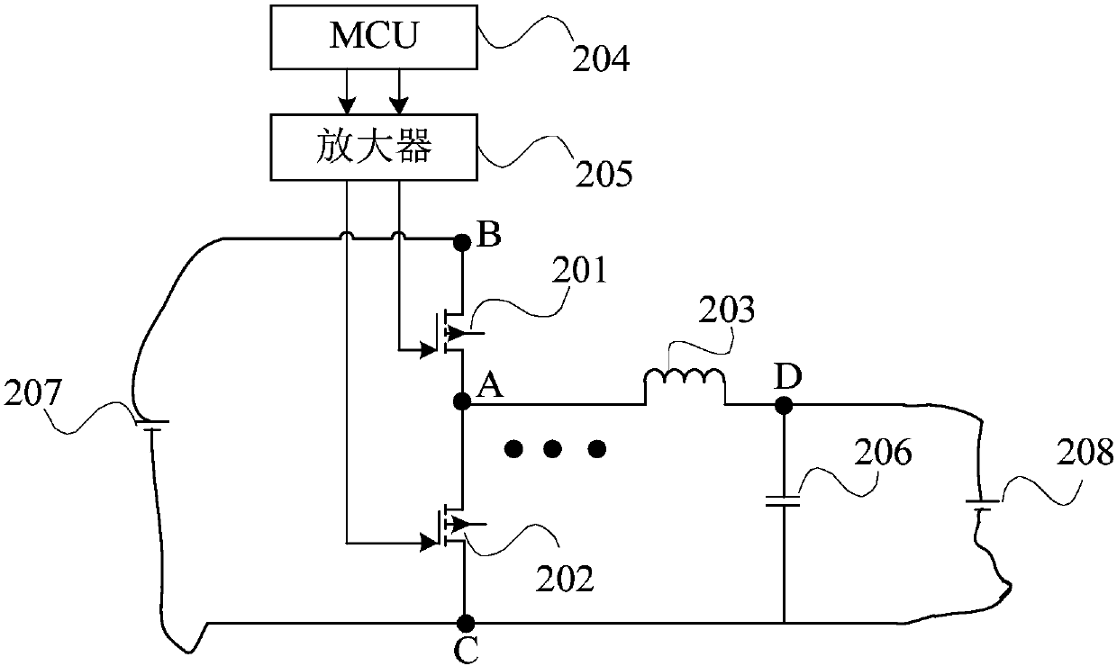
[0046] The embodiment of the present invention provides a converter, such as figure 2 As shown, it includes a plurality of parallel half-bridges, each half-bridge includes a first MOS transistor 201, a second MOS transistor 202 and a first inductor 203; the drain of the first MOS transistor 201 and the second MOS transistor 202 The source is connected to the first node A, one end of the first inductor 203 is connected to the first node A, the sources of all the first MOS transistors 201 in the converter are con...


PUM


Abstract

The invention provides a converter which comprises a plurality of parallel half-bridges. Each half-bridge comprises a first MOS transistor, a second MOS transistor and a first inductor. The gate electrode of the first MOS transistor is connected with a first control signal. The gate electrode of the second MOS transistor is connected with a second control signal. The first control signal is complementary with the second control signal for reducing cost. Alternatively, when the average current which flows over the first inductor in one period is larger than critical switching current, the firstcontrol signal and the second control signal are complementary signals. When the average current which flows over the first inductor in one period is smaller than the critical switching current, thefirst control signal and the second control signal are independent signals. Hereon, the duty ratio of the first control signal is determined by the required load voltage, and the duty ratio of the second control signal is determined by the required load voltage, the input voltage and the duty ratio of the first control signal. The converter has advantages of reducing cost, preventing reverse current in light load and improving efficiency.

Description

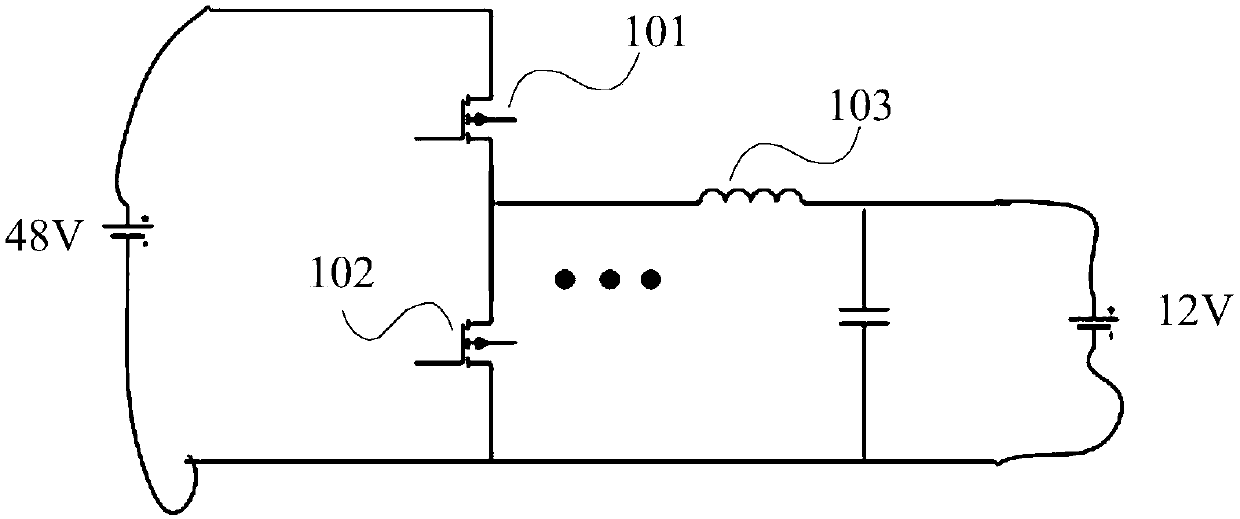
technical field [0001] The invention relates to a new energy system, in particular to a converter and a control method thereof. Background technique [0002] The 48V light-hybrid system is a very practical architecture in the current new energy market. It has the characteristics of simple modification and low cost, and is an important factor attracting various OEMs to start deploying such models. There is an important energy conversion component DCDC converter in the 48V system, and its topology is as follows figure 1 As shown, it includes a plurality of parallel half-bridges, and each half-bridge includes a first MOS transistor 101, a second MOS transistor 102 and a first inductor 103, which mainly realize the conversion of 48V and 12V DC power in the vehicle; when the vehicle is just started, The 12V power is converted to the 48V side through the Boost mode, and the capacitor on the motor controller is charged to complete the pre-charging function. During the driving pro...

Claims


Application Information

Patent Timeline
IPC IPC(8): H02M3/155
CPCH02M3/155H02M1/0003
Inventor 孙政臣黄昊
Owner UNITED AUTOMOTIVE ELECTRONICS SYST
Learn More