
Matching circuit

A matching circuit and matching module technology, applied in the field of matching circuits, can solve the problems of complex circuits, high isolation, large circuit size, etc., and achieve the effect of simplifying matching circuits and reducing costs

Inactive Publication Date: 2018-03-06
ZTE CORP
View PDF0 Cites 0 Cited by
  • Summary
  • Abstract
  • Description
  • Claims
  • Application Information

AI Technical Summary

Problems solved by technology

(2) Dual-band power amplifier with left and right hand composite materials: use left and right hand composite materials to design a dual-band power amplifier based on the principle of composite left and right hand transmission lines (CRLH TLs), and its circuit is more complicated
The frequency band switchable power amplifier uses the switch conversion method to match in the two frequency bands, which requires low insertion loss and high isolation at the switch. In addition, the frequency band switchable power amplifier needs to be individually set for each operating frequency point. Circuit, the size of the circuit is large, and the use of left and right hand composite materials to design the circuit requires the synthesis of new materials, which is costly

Method used


Image

  • Matching circuit
  • Matching circuit
  • Matching circuit

Examples


Embodiment Construction

[0022] It should be understood that the specific embodiments described here are only used to explain the present invention, not to limit the present invention.

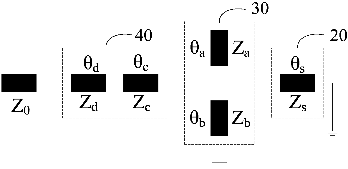
[0023] Such as figure 1 As shown, an embodiment of a matching circuit of the present invention is shown. The matching circuit of this embodiment is connected between the amplifier 10 and the input circuit 50, and the matching circuit includes: a real part equal module 20, an imaginary part elimination module 30 and a real part matching module 40, wherein the amplifier 10 is successively equal to the real part module 20 , the imaginary part elimination module 30 , the real part matching module 40 and the input circuit 50 are connected, and the input circuit 50 is used to send radio frequency signals of two different frequency points to the amplifier 10 .

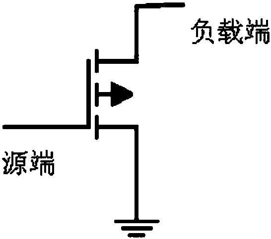
[0024] Amplifier 10 is structured as figure 2 As shown, the signal is input from the source and output from the load after being amplified. When the real part eq...


PUM


Abstract

The invention discloses a matching circuit, the matching circuit is connected between an amplifier and an input circuit, the matching circuit comprises a real part equality module, an imaginary part elimination module and a real part matching module, the amplifier is orderly connected with the real part equality module, the imaginary party elimination module, the real part matching module and theinput circuit; the input circuit is used for sending radio frequency signals of two different frequency points to the amplifier; when the real part equality module is connected with a source end of the amplifier, a target real number input impedance value is obtained through matching of input impedance values of the source end of the amplifier at two different frequency points; and when the real part equality module is connected with a load end of the amplifier, a target output real number impedance value is obtained through matching of output impedance values of the load end of the amplifierat two different frequency points. According to the invention, the matching circuit is simplified, and cost is reduced.

Description

technical field [0001] The invention relates to the technical field of wireless communication, in particular to a matching circuit. Background technique [0002] As one of the important modules of the transmission components of the wireless communication system, the RF power amplifier's performance will directly affect the quality of the communication signal. With the development of communication technology, people are constantly pursuing low-power, miniaturized, and multi-functional radio frequency devices. The RF power amplifier has the characteristics of high energy consumption and large size. The traditional power amplifier can only satisfy the power amplification function of a single frequency band to be able to amplify the function in multiple frequency bands, including the following methods: [0003] (1) Band-switchable power amplifier: A micro-electro-mechanical system is used to perform network matching on different frequency bands, and a band-switchable, compresse...

Claims


Application Information

Patent Timeline
IPC IPC(8): H03F1/56
CPCH03F1/56
Inventor 张冬生
Owner ZTE CORP
Learn More