Oil residue filtering device for production of chemical raw materials

A technology of chemical raw materials and filtration devices, applied in the direction of filtration and separation, membrane filters, fixed filter elements, etc., can solve problems such as low work efficiency, affecting product quality, affecting raw material quality, etc., to increase the oil filtering effect and structure Simple and practical effect

Inactive Publication Date: 2018-03-09
JIANGSU JIHUA CHEMICAL CO LTD
View PDF3 Cites 2 Cited by
  • Summary
  • Abstract
  • Description
  • Claims
  • Application Information

AI Technical Summary

Problems solved by technology

The main development trends of modern chemical production technology are: the large-scale production of basic chemical industry, the full utilization of raw materials and by-products, the adoption of new raw material routes and new catalysts (including new reactions), the reduction of energy consumption, the prevention of environmental pollution, Automation of production control, optimization of production, etc.; in the production of chemical raw materials, a large amount of oil residue is likely to be produced, which affects the quality of raw materials. It is necessary to filter the oil residue. In the prior art, the oil residue is mainly filtered through gauze. The efficiency is low and can only filter part of the oil residue, which affects the quality of the product and needs to be improved

Method used


Image

  • Oil residue filtering device for production of chemical raw materials
  • Oil residue filtering device for production of chemical raw materials

Examples


Embodiment Construction

[0017] In order to make the object, technical solution and advantages of the present invention clearer, the present invention will be further described in detail below in conjunction with the accompanying drawings and embodiments. It should be understood that the specific embodiments described here are only used to explain the present invention, not to limit the present invention.

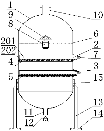
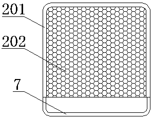
[0018] Such as Figure 1-2 As shown, the oil residue filter device for chemical raw material production according to the present invention includes: an equipment housing 1, an upper filter plate and 2 lower filter plates 3, an upper support plate 4 is arranged below the upper filter plate 2, and the A lower support plate 5 is arranged below the lower filter plate 3, a pull rod 7 is arranged on the upper filter plate 2 and the lower filter plate 3, and a motor 8 is installed and fixed above the upper filter plate 2 by a fixing frame 6, and the motor 8 is installed and fixed on the upper filter plate...


PUM


Abstract

The invention relates to an oil residue filtering device for production of chemical raw materials. The oil residue filtering device comprises an equipment shell body, an upper filtering plate and a lower filtering plate, wherein an upper supporting plate is arranged below the upper filtering plate; a lower supporting plate is arranged on the lower surface of the lower filtering plate; pull rods are arranged on the upper filtering plate and the lower filtering plate; a motor is mounted and fixed above the upper filtering plate through a fixing frame; a conical flow divider is mounted above themotor; a material inlet is formed in the top of the equipment shell body and a material outlet is formed in the bottom end of the equipment shell body; a stop valve is mounted below the material outlet; supporting legs are further arranged at the lower end of the equipment shell body; a bottom plate is fixed at the lower ends of the supporting legs; base plates are arranged at connecting parts ofthe supporting legs and the equipment shell body. According to the oil residue filtering device provided by the invention, two layers of the filtering plates which can be movably taken out are additionally arranged in the shell body and can be used for filtering oil residues layer by layer, so that the oil filtering effect is increased; the conical flow divider is arranged in the shell body so that raw materials are dispersed in an oil filtering process, so that a condition that filtering residues are accumulated to cause blocking so that an oil filtering effect is influenced is prevented; theoil residue filtering device provided by the invention has a relatively simple structure and relatively high practicability and is suitable for popularization and application.

Description

technical field [0001] The invention relates to the field of chemical equipment, in particular to an oil residue filter device for chemical raw material production. Background technique [0002] Chemical production technologies are usually proposed for certain products or raw materials, such as the production of vinyl chloride, the synthesis of methanol, the production of sulfuric acid, and coal gasification. Therefore, it has the particularity of individual production; however, its content generally covers aspects such as: selection of raw materials and production methods, process organization, role of equipment used (reactors, separators, heat exchangers, etc.), structure and operation , the impact of catalysts and other materials, the determination of operating conditions, production control, product specifications and separation and utilization of by-products, as well as issues such as safety technology and technical economy. The realization of modern chemical productio...

Claims


Application Information

Patent Timeline
Patent Type & Authority Applications(China)
IPC IPC(8): B01D29/58B01D29/90B01D29/01
CPCB01D29/58B01D29/01B01D29/906B01D2201/44
Inventor 陈小勇
Owner JIANGSU JIHUA CHEMICAL CO LTD
Why Eureka
Try Eureka