

Heating stirrer for low viscous reagents
A heating and stirring technology with low viscosity, applied in the chemical field, can solve the problems of long test cycle, deviation of test results, and difficulty in meeting the test detection of large-capacity liquids, so as to improve the stirring efficiency, reduce the weight and shorten the stirring time. Effect
- Summary
- Abstract
- Description
- Claims
- Application Information
AI Technical Summary
Problems solved by technology
Method used
Image

Examples
Embodiment 1
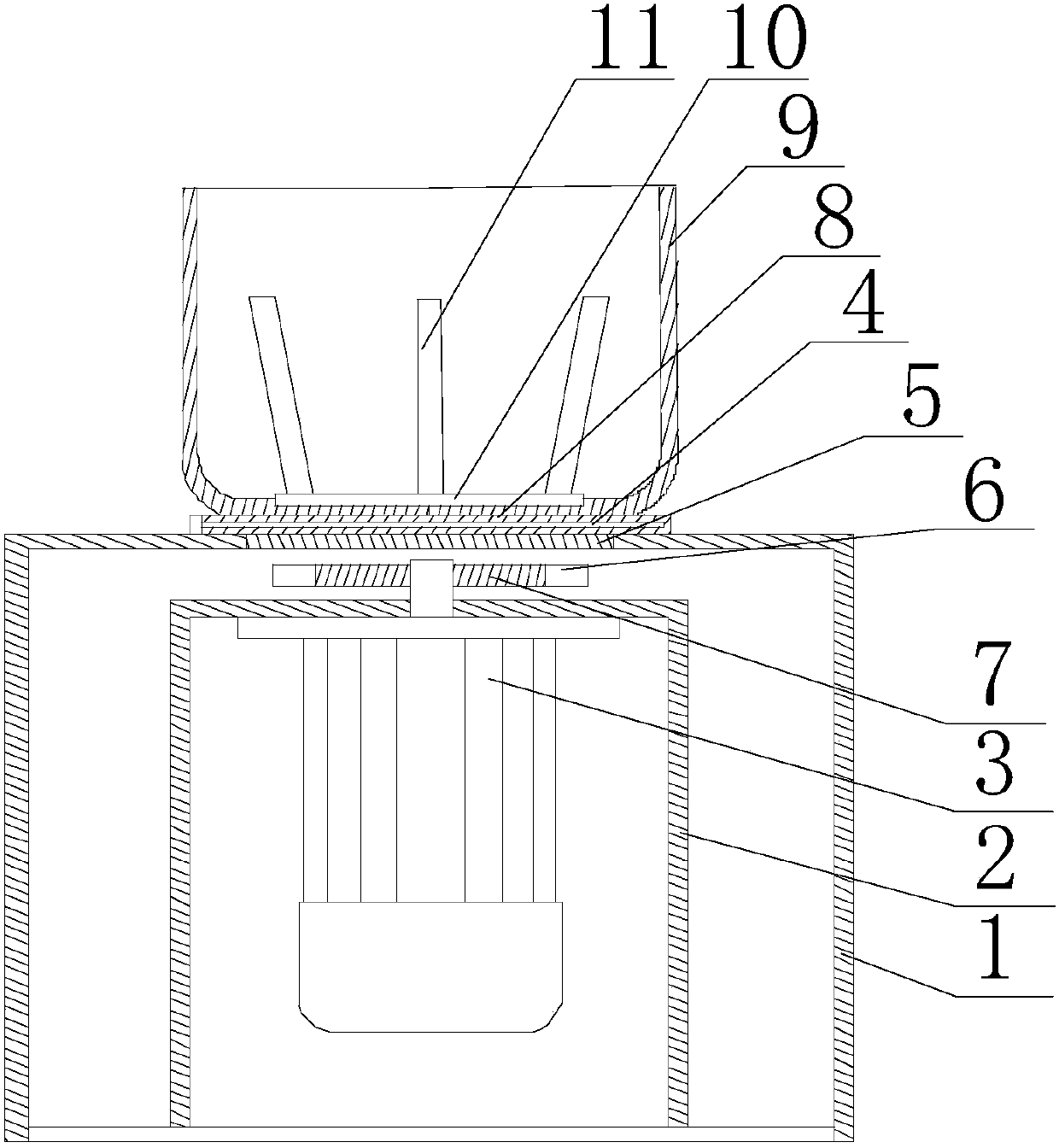
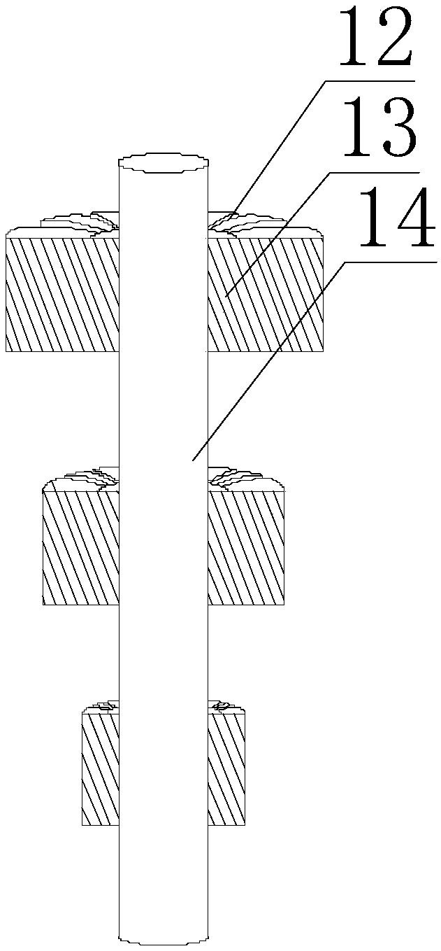
[0021] Such as Figure 1~2 As shown, the present embodiment includes a support base 1 and an installation base 2 arranged inside the support base 1, a motor 3 is arranged inside the installation base 2, an opening is provided on the upper end surface of the installation base 2, and the output end of the motor 3 moves through the The opening extends to the inside of the support seat 1, and a turntable 7 is installed on the extension of the output end of the motor 3, and a plurality of magnetic strips 6 are arranged on the upper end surface of the turntable 7 along the circumference of the turntable 7. On the support seat 1 The upper end surface is provided with a through hole, the turntable 7 is placed between the through hole and the opening, a heat conduction plate 8 is arranged at the upper end of the through hole, and a non-magnetic heat shield 5 is arranged at the lower end of the through hole, and in the heat conduction plate 8 A plurality of heating pipes 4 are provided,...
PUM
 Abstract
Description
Claims
Application Information