Pipeline iron scrap cleaner

A technology of remover and iron filings, which is applied in the field of iron filings and welding slag removal in pipelines. It can solve the problems that iron filings cannot be removed, welding slag is not easy to wash, and iron filings cannot be removed in time, so as to save pigging costs and have a simple structure. , strong practical effect

Inactive Publication Date: 2018-03-09
PETROCHINA CO LTD
View PDF7 Cites 0 Cited by
  • Summary
  • Abstract
  • Description
  • Claims
  • Application Information

AI Technical Summary

Problems solved by technology

[0004] In order to solve the technical problems in the prior art that the iron filings cannot be removed in time after the pipe is cut, the iron filings blocking the water meter and the throttle opening of the regulating valve cannot be removed, and the welding slag is not easy to wash, the present invention provides a simple and effective cleaning method for cleaning the pipeline. Pipeline iron filings remover for residual iron filings and welding slag

Method used


Image

  • Pipeline iron scrap cleaner
  • Pipeline iron scrap cleaner

Examples


Embodiment Construction

[0035] In order to make the technical solutions and advantages of the present invention clearer, the embodiments of the present invention will be further described in detail below in conjunction with the accompanying drawings. Unless otherwise defined, all technical terms used in the embodiments of the present invention have the same meanings as commonly understood by those skilled in the art.

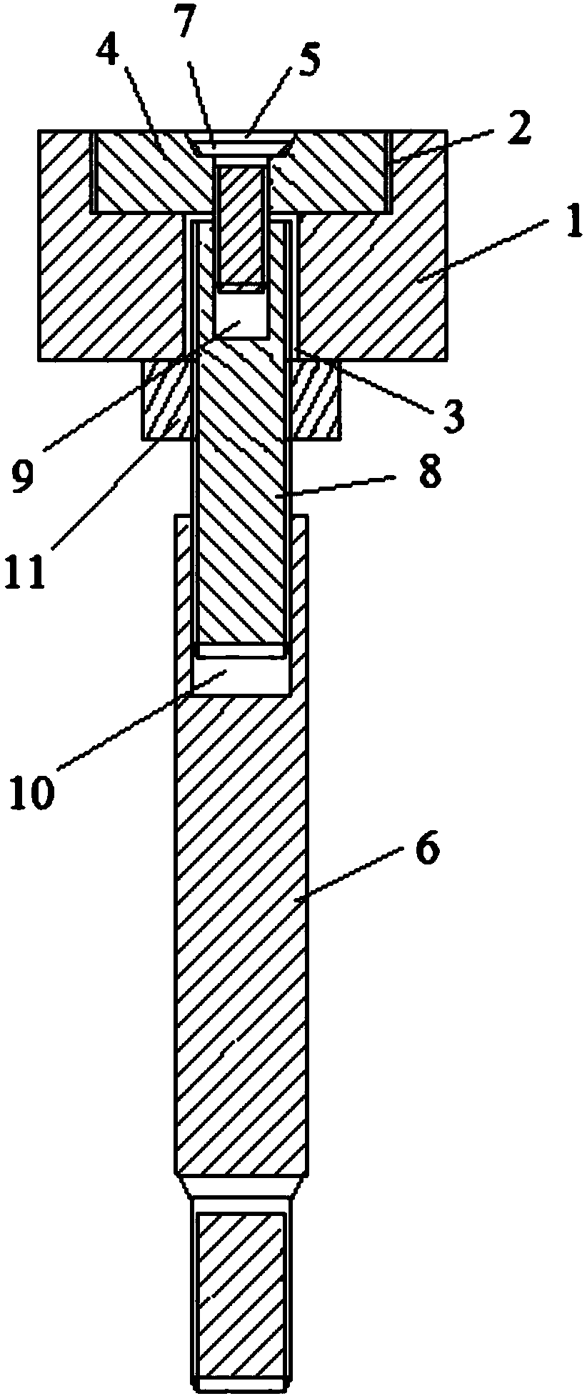
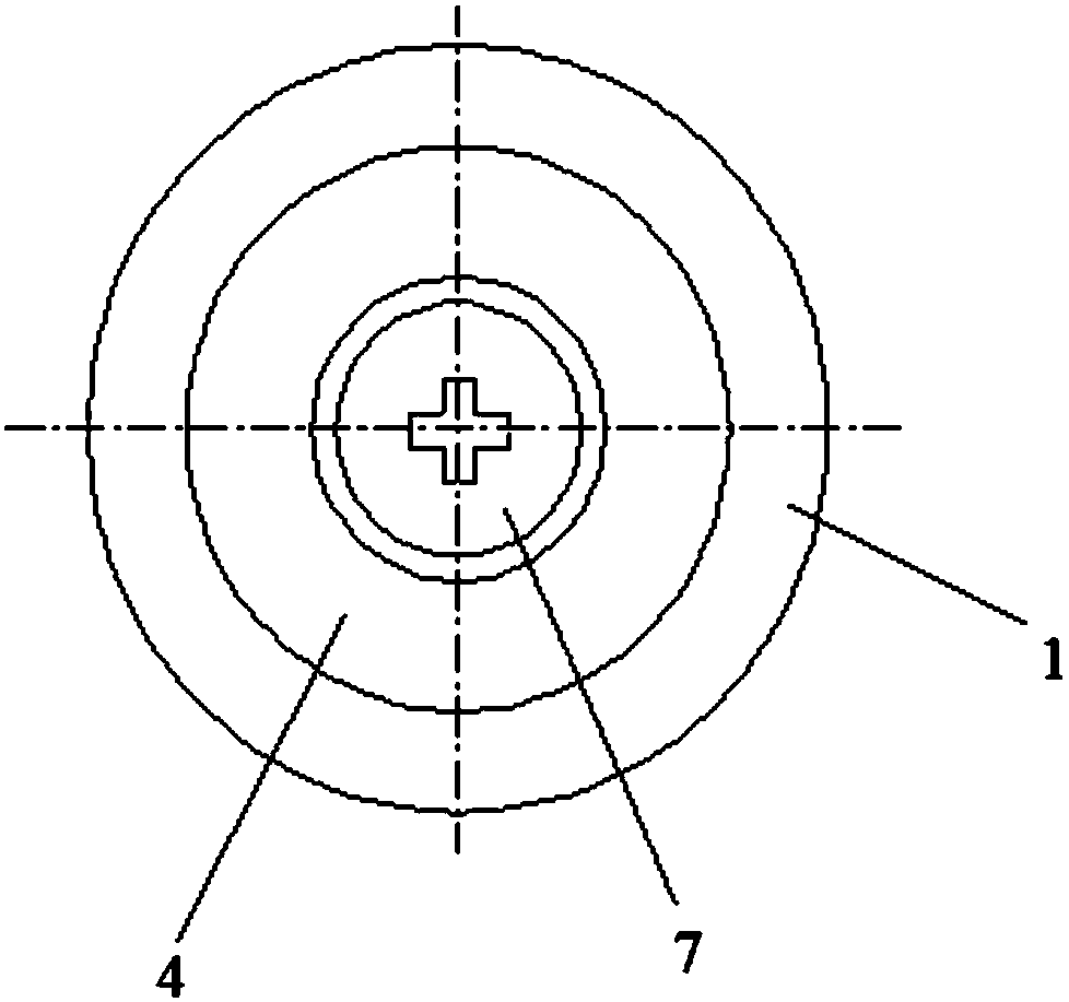
[0036] An embodiment of the present invention provides a pipeline iron filings remover, such as figure 1 combine figure 2 as shown, figure 1 It is a schematic cross-sectional structural schematic diagram of a front view of a pipeline iron filings remover provided by an embodiment of the present invention; figure 2 It is a schematic top view structure diagram of a pipe iron filings remover provided by an embodiment of the present invention. This pipe chip remover includes:

[0037] A protection ring 1, the upper end of the protection ring 1 has a first cavity 2, and the lower end ...


PUM


Abstract

The invention discloses a pipeline iron scrap cleaner, and belongs to the technical field of iron scraps and welding slag cleaning in pipelines. The pipeline iron scrap cleaner includes a protection ring, a cleaning head, a cleaning rod and a fixing screw. The upper end of the protection ring is provided with a first cavity, and the lower end of the protection ring is provided with a second cavitycommunicating with the first cavity. The diameter of the first cavity is greater than the diameter of the second cavity. The cleaning head is located in the first cavity of the protection ring, and the cleaning head is a magnet and is provided with a through hole communicating with the second cavity. The cleaning rod is located below the second cavity of the protection ring. The fixing screw passes through the through hole of the cleaning head and the second cavity of the protection ring to connect to the cleaning rod. The pipeline iron scrap cleaner can timely clean the iron scraps splashedinto a pipeline when the pipeline is cut, and quickly clean the iron scraps and welding slag which block a water meter and a throttle orifice of a regulating valve, thereby saving the cleaning cost ofthe pipeline and being conductive to the safety of the pipeline.

Description

technical field [0001] The invention relates to the technical field of iron filings and welding slag removal in pipelines, in particular to a pipeline iron filings remover. Background technique [0002] In industrial production, gas-carrying operations on pipelines mainly involve gas cutting and welding. Usually, gas cutting or tee welding is performed on pipelines. When opening with gas cutting, a lot of iron filings will be blown into the pipe while cutting, and some iron filings will remain in the pipe due to grinding before gas welding. When the gas-carrying operation is completed and the pipeline (including air pipes, oil pipes, water pipes, etc.) resumes work, iron filings will be blown to the downstream pipeline equipment (such as water meters of oil production well stations, orifices of regulating valves) due to the impact of air flow or fluid. In the interior, especially after the welding of low-pressure pipelines is completed, there is no filtering equipment downs...

Claims


Application Information

Patent Timeline
Patent Type & Authority Applications(China)
IPC IPC(8): B08B9/043
Inventor 闻伟董洪青劳丽珍姜新红周瑞李雄祁长海杨亚博赵磊
Owner PETROCHINA CO LTD
Why Eureka
Try Eureka