Boiler with annular upper furnace body deashing chamber

A furnace body and ash cleaning technology, which is applied in the boiler field, can solve the problems of waste of resources, long time, delay in heating, etc., and achieve the effects of safe and reliable use, extended service life, and extended service life

Inactive Publication Date: 2010-12-22
吴军
View PDF5 Cites 0 Cited by
  • Summary
  • Abstract
  • Description
  • Claims
  • Application Information

AI Technical Summary

Problems solved by technology

But the shortcoming of this reciprocating flue boiler structure with the upper and lower flues is that the smoke and dust from coal combustion in the furnace will be deposited at the intersection of the upper and lower flues due to the slowing down of the flow velocity, and the smoke will be destroyed for a long time. To block the intersection of the upper and lower

Method used


Image

  • Boiler with annular upper furnace body deashing chamber
  • Boiler with annular upper furnace body deashing chamber
  • Boiler with annular upper furnace body deashing chamber

Examples


Embodiment Construction

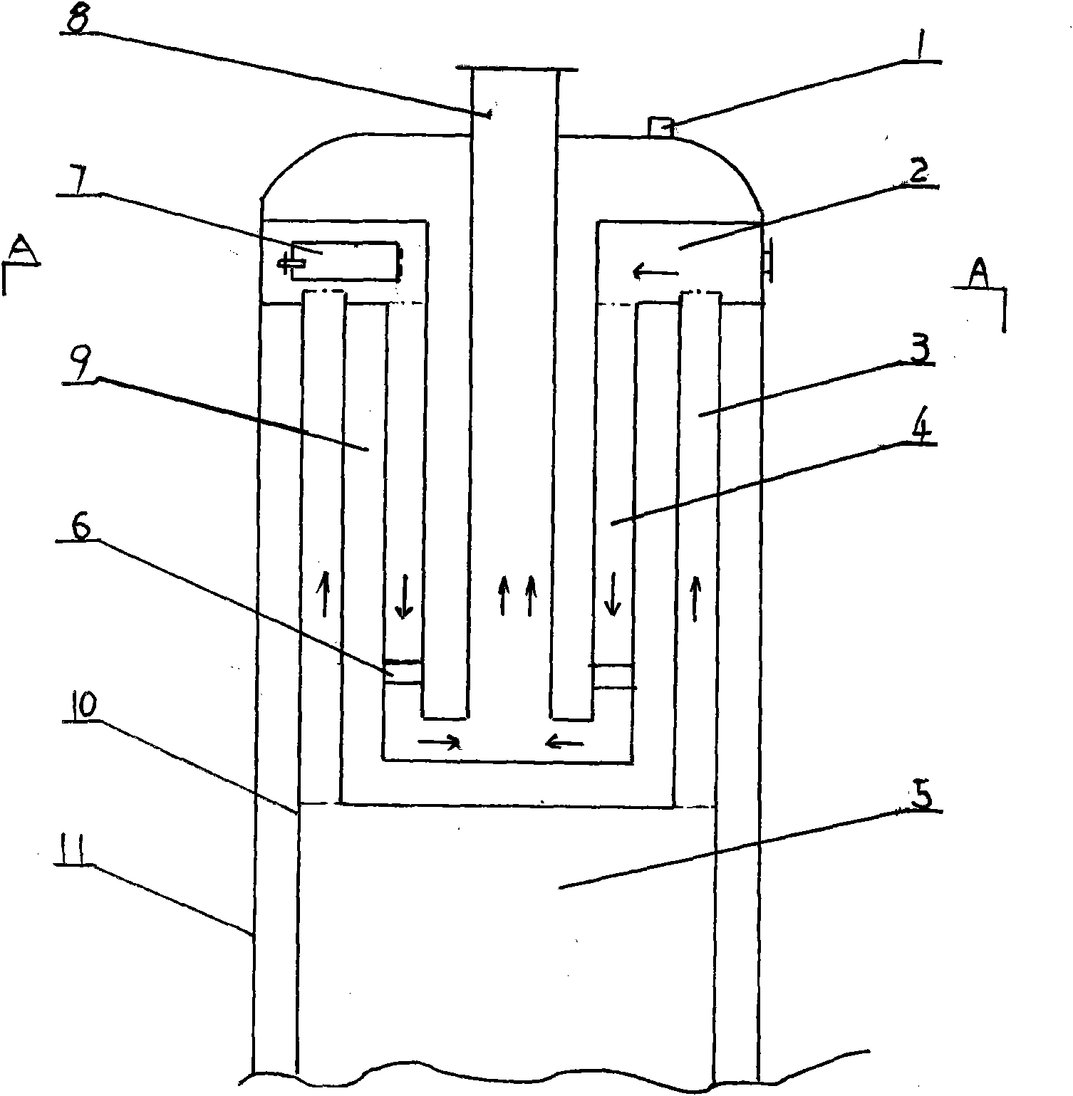
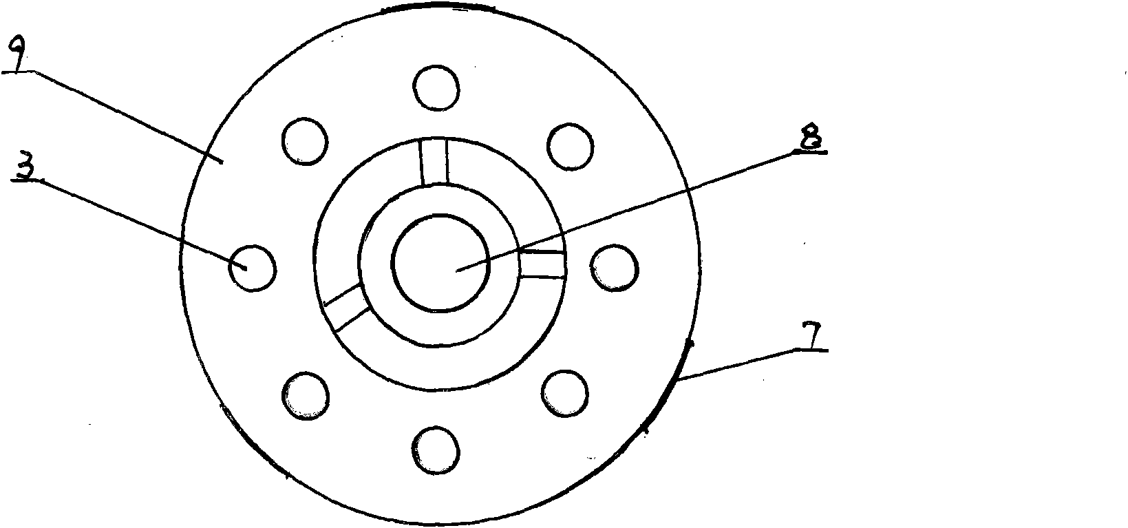
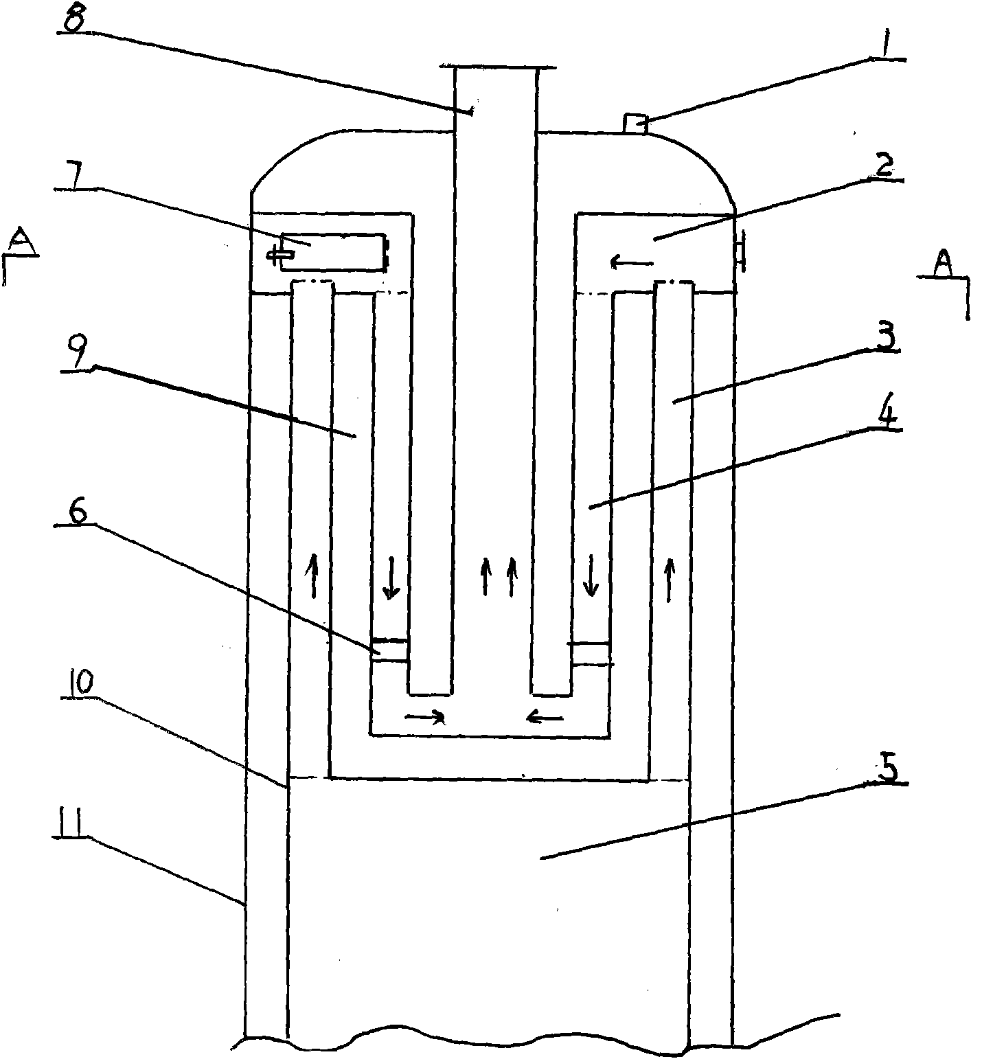
[0008] Such as Figure 1 to Figure 2 As shown, since the design of the present invention is mainly at the intersection of the upper and lower flue passages on the top of the furnace body, the rest of the furnace body is omitted. The water outlet 1, the ascending flue 3, the descending flue 4, the water liner 9, the furnace body 11, the furnace 5, the water pipe 6, the flue pipe 8 and the water liner layer 10 of the present invention are traditional reciprocating flue type boiler structures , so it will not be described in detail.

[0009] The present invention is composed of a furnace body, a furnace and a water outlet. An annular upper furnace body ash cleaning chamber 2 is arranged in the water bladder at the upper end of the furnace body. The flue is usually a fire pipe. The upper end of the descending flue communicates with the ring-shaped upper furnace body cleaning chamber, and the descending flue is usually an annular body descending flue. At least one soot-cleaning ...


PUM


Abstract

The invention relates to a boiler with an annular upper furnace body deashing chamber, comprising a furnace body, a furnace cavity and a water outlet, wherein a water tank positioned at the upper end of the furnace body is internally provided with the annular upper furnace body deashing chamber; the upper end of each uplink flue is communicated with the annular upper furnace body deashing chamber, and the upper end of each downlink flue is communicated with the annular upper furnace body deashing chamber; the furnace body positioned on the side edge of the annular upper furnace body deashing chamber is provided with at least one deashing door; and the 2-3 deashing doors are distributed at intervals. The invention can conveniently and effectively clean the smoke dust positioned on the uplink flues and the downlink flues and has the advantages of simple structure, low cleaning cost, good safety and greatly prolonged service life of the boiler.

Description

technical field [0001] The invention belongs to a boiler with a dust-cleaning chamber on an annular upper furnace body. Background technique [0002] The traditional reciprocating flue boiler structure uses the upper and lower flues to pass through the water tank at the upper end of the boiler to increase the heat absorption area in the water tank and improve thermal efficiency. But the shortcoming of this reciprocating flue boiler structure with the upper and lower flues is that the smoke and dust from coal combustion in the furnace will be deposited at the intersection of the upper and lower flues due to the slowing down of the flow velocity, and the smoke will be destroyed for a long time. To block the intersection of the upper and lower flues, it is necessary to cut and dissect the boiler to expose the upper and lower flues to clean the smoke and dust. Repairing in this way will not only cost too much to dismantle the boiler, but also take too long, and the user cannot a...

Claims


Application Information

Patent Timeline
IPC IPC(8): F24H1/36F24H9/00
Inventor 吴军王彦飞
Owner 吴军
Why Eureka
Try Eureka