Supercharge Your Innovation With Domain-Expert AI Agents!

Electric horn driving circuit of electric vehicle

A technology for driving circuits and electric horns, applied in vehicle parts, bicycle accessories, audio signals, etc., can solve the problem of difficult to adjust the sound of the horn, and achieve the effect of adjusting the sound

Pending Publication Date: 2018-03-09
徐州荣立达电子科技有限公司
View PDF0 Cites 0 Cited by
  • Summary
  • Abstract
  • Description
  • Claims
  • Application Information

AI Technical Summary

Problems solved by technology

However, it is difficult to adjust the sound of the speaker after the existing electric speaker drive circuit is packaged.

Method used


Image

  • Electric horn driving circuit of electric vehicle

Examples


Embodiment Construction

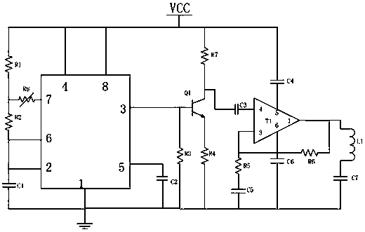
[0007] The present invention will be further explained below in conjunction with the accompanying drawings.

[0008] Such as figure 1 As shown, an electric car horn driving circuit includes resistors R1-R7, variable resistors R8, capacitors C1-C7, inductor L1, transistor Q1, amplifier T1 and a 555 timer chip. Amplifier T1 chooses the feedback amplifier of model AD8065, its common-mode rejection ratio can reach -100dB, and the output voltage can reach up to 24V.

[0009] The fourth and eighth pins of the 555 timer chip are connected to the power supply VCC, and the seventh pin of the 555 timer chip is connected to the power supply VCC through the series branch of the variable resistor R8 and the resistor R1. The second and sixth pins of the 555 timer chip are also connected to one end of the capacitor C1 and the resistor R2 at the same time, the other end of the capacitor C1 is grounded, and the other end of the resistor R2 is connected to the common end of the variable resist...


PUM


Abstract

The invention discloses an electric horn driving circuit of an electric vehicle. An audio generator of an electric horn is designed by utilizing a 555 timer and can output periodic pulse signals to trigger a transistor to run to finally make a horn diaphragm vibrate regularly. In the circuit, when a power supply VCC charges a capacitor C1 through resistors R1 and R2 and the voltage of the capacitor C1 reaches 2 / 3 of that of the power supply, a third pin of a chip outputs high level, the capacitor C1 stops being charged, and when the voltage of the capacitor C1 reduces to 1 / 3 of that of the power supply, the third pin of the chip outputs low level, so that the periodic pulse signals are achieved; meanwhile, a variable resistor R8 is introduced among a seventh pin of the chip and the resistors R1 and R2 so that the resistors R1 and R2 can be adjusted by adjusting the resistor R8, the time of charging and discharging the capacitor C1 is adjusted, and therefore the purpose of adjusting sound production is achieved by changing the duty ratio output by the third pin of the chip.

Description

technical field [0001] The invention relates to an electric horn driving circuit of an electric vehicle. Background technique [0002] Conventional horns are basically pot-shaped electric horns, which mainly include electromagnet coils, diaphragms, contacts and other components. The sounding principle is basically to control the contact action of the electromagnet coil to drive the diaphragm to vibrate, and the frequency vibration is generated by the sounding board to produce sound. During the use of this kind of horn, if the horn is pressed and held for a long time, the contacts are prone to burning, which will affect the life of the horn. The main reason for burning is that when the electromagnet coil is connected to the circuit, the magnetic energy stored in the coil emits sparks on the contact surface at the moment the contact is disconnected. In order to overcome this problem, an electric horn with a non-contact structure has been developed on the market, and the phys...

Claims


Application Information

Patent Timeline
Patent Type & Authority Applications(China)
IPC IPC(8): B60Q5/00B62J3/00
CPCB62J3/00B60Q5/00
Inventor 李全敏
Owner 徐州荣立达电子科技有限公司
Features
  • R&D
  • Intellectual Property
  • Life Sciences
  • Materials
  • Tech Scout
  • Unparalleled Data Quality
  • Higher Quality Content
  • 60% Fewer Hallucinations
Learn More