Cantilever crane with suspended car

A technology for hanging trolleys and cranes, which is applied in the direction of walking bridge cranes, cranes, and traveling mechanisms. It can solve the problems of inability to directly hand over goods in the next workshop, waste of manpower and material resources, and inconvenience, and achieve novel structure, smooth operation, and guaranteed use. safe effect

Inactive Publication Date: 2018-03-09
谢新华
View PDF0 Cites 0 Cited by
  • Summary
  • Abstract
  • Description
  • Claims
  • Application Information

AI Technical Summary

Problems solved by technology

[0002] Existing bridge cranes are used in enterprise workshops. Some workshops are equipped with many machine tools for processing and production. Products and raw materials need to be transported to the next workshop or other departments in real time; the hooks of the cranes in the workshop are hung from the trolley. For hoisting goods, the trolley can only run back and forth along the double girders of the crane, and the crane can only run back and forth along the cart rails on the cross columns on both sides of the workshop, so that the range of goods that the crane hook can lift is within the distance between the two cart rails in the workshop. Within the plane surrounded by the two ends, when the goods at the edge of the plane need to be hoisted, the hook will be pulled obliquely, and the items farther away from this plane (such as outside the workshop door, outside the span) cannot be hoisted. At this time, it can only be transferred with the help of other transportation equipment. Usually, the car drives into the workshop to lift the goods under the hook. Go to the hook to hand over the goods, and some set up a special cantilever crane at the workshop door (or workshop aisle) to transfer and dispatch the goods outside the workshop, first hoist the goods into the place where the crane hook of the workshop can reach , and then the cargo is hoisted by the crane to other stations in the workshop. The existing bridge crane used in this working condition cannot directly transfer the cargo with the workshop next door, and must use other transportation equipment to schedule operations, which brings considerable inconvenience. It also wastes manpower and material resources

Method used


Image

  • Cantilever crane with suspended car
  • Cantilever crane with suspended car
  • Cantilever crane with suspended car

Examples


Embodiment approach

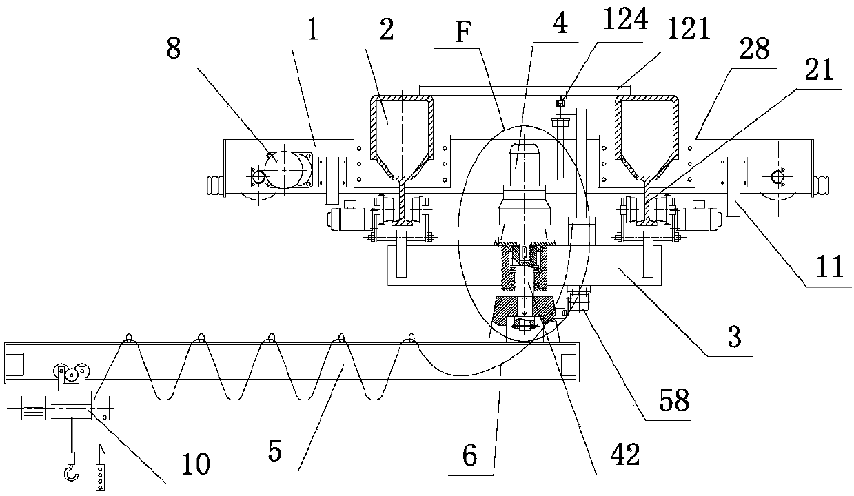
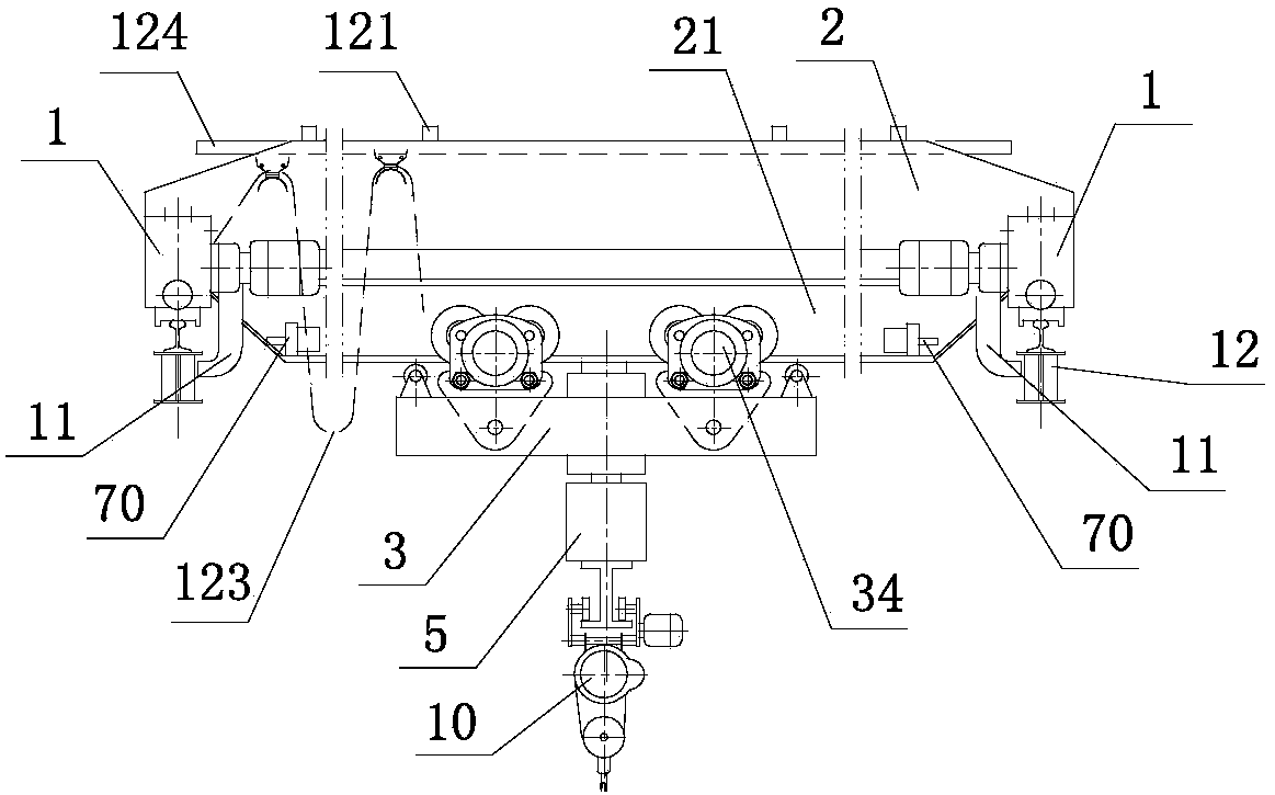
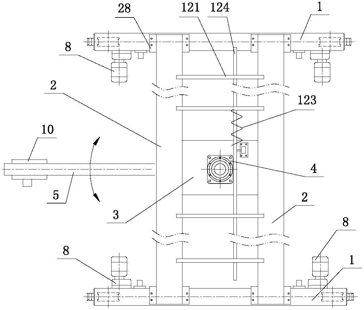
[0035] like figure 1 , figure 2 , image 3 As shown, a cantilever crane with a suspended trolley, the double-girder bridge includes an end girder 1 and a main girder 2; it is characterized in that: both ends of the end girder 1 are provided with a cart driving device 8 with shaft-connected wheels The bottom of the main beam 2 is provided with a track 21; the two ends of the track are connected to the stop device 70; the two tracks 21 are connected with the suspension trolley 3, and can run along the track; the suspension trolley 3 is provided with There is a rotating mechanism 4; the boom shaft 42 in the rotating mechanism is connected to the cantilever member 5; a rotation limiting device 58 is provided between the cantilever member and the suspension trolley 3; an electric hoist 10 is installed on the cantilever member 5, The electric hoist can move back and forth horizontally along the cantilever beam; the cantilever beam is located under the main beam and can be stretch...


PUM


Abstract

The application discloses a cantilever crane with a suspended trolley, which includes a double-girder bridge frame; the double-girder bridge frame includes an end beam and a main beam; both ends of the end beam are provided with cart driving devices and safety hooks; Rails are provided; the two ends of the rails are connected with car stoppers; the two rails are connected with suspension trolleys and can run along the rails; the suspension trolleys are provided with a rotation mechanism; the boom shaft in the rotation mechanism is connected to the cantilever member; A rotation limit device is connected to the cantilever member; an electric hoist is installed on the cantilever member, and can move back and forth horizontally along the cantilever beam; The guide cable rail is connected under the frame; the hanging cable on the guide cable rail is electrically connected with the suspension trolley.

Description

technical field [0001] The present application relates to the field of cranes, in particular to a jib crane with a suspension trolley. Background technique [0002] Existing bridge cranes are used in enterprise workshops. Some workshops are equipped with many machine tools for processing and production. Products and raw materials need to be transported to the next workshop or other departments in real time; the hooks of the cranes in the workshop are hung from the trolley. For hoisting goods, the trolley can only run back and forth along the double girders of the crane, and the crane can only run back and forth along the cart rails on the cross columns on both sides of the workshop, so that the range of goods that the crane hook can lift is within the distance between the two cart rails in the workshop. Within the plane surrounded by the two ends, when the goods at the edge of the plane need to be hoisted, the hook will be pulled obliquely, and the items farther away from th...

Claims


Application Information

Patent Timeline
IPC IPC(8): B66C17/04B66C11/10B66C9/14B66C9/16B66C9/18B66C7/04B66C7/16B66C23/84B66C23/94B66C13/12
CPCB66C17/04B66C7/04B66C7/16B66C9/14B66C9/16B66C9/18B66C11/10B66C13/12B66C23/84B66C23/94B66C2700/0342B66C2700/035
Inventor 谢新华
Owner 谢新华
Why Eureka
Try Eureka