Eureka AIR delivers breakthrough ideas for toughest innovation challenges, trusted by R&D personnel around the world.

Shock insulation device for railway bridge

A technology for bridge use and seismic isolation, applied in the field of bridge shock absorption, can solve the problems of limited applicability and practicability, limited shock absorption effect, etc., and achieve the effect of good practicability, reasonable structure setting, and good seismic isolation performance.

Pending Publication Date: 2018-03-09
温州卡耐夫电器有限公司
View PDF0 Cites 6 Cited by
  • Summary
  • Abstract
  • Description
  • Claims
  • Application Information

AI Technical Summary

Problems solved by technology

[0002] With the maturity of bridge and road technology in our country, various bridges and building structures develop rapidly. In order to ensure the service life and reliability of bridges, there are generally corresponding shock-absorbing structures. The common ones on the market are natural rubber bearings and Lead-core rubber bearings are mainly installed between the upper part of the bridge and between the piers and abutments, which can reduce the seismic load to a certain extent and reduce the damage of the seismic load to the bridge structure, but its shock absorption effect is relatively limited. At the same time that the city brings convenient transportation, it will bring certain vibration and noise effects, so the applicability and practicality are limited

Method used


Image

  • Shock insulation device for railway bridge

Examples


Embodiment 1

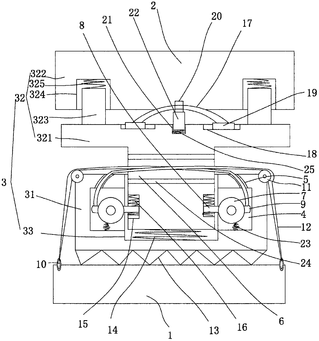
[0014] figure 1 An embodiment of the invention is shown in which figure 1 It is a schematic diagram of the structure of the present invention.

[0015] See figure 1 , a seismic isolation device for rail bridges, comprising a base 1, a shock-absorbing support seat 2 and a shock-absorbing structure 3, the shock-absorbing structure 3 is located between the base 1 and the shock-absorbing support seat 2, and when in use, the base is fixed with On the bridge pier and the shock-absorbing support seat is connected to the bottom of the bridge, the shock-absorbing structure 3 includes a shock-absorbing seat 31, a shock-absorbing frame 32 arranged on the shock-absorbing seat 31, and the shock-absorbing support seat 3 is fixed on the shock-absorbing seat 31. The top of the shock mount 32 is provided with a shock-absorbing chamber 33 with an opening on the top surface in the shock-absorbing seat 31, and at least two pressure chambers 4 are evenly arranged on the inner wall of the shock-a...


PUM


Abstract

The invention discloses a shock insulation device for a railway bridge. The shock insulation device comprises a base, a shock-absorbing support seat and a shock absorbing structure, wherein the shockabsorbing structure comprises a shock absorbing seat and a shock absorbing frame arranged on the shock absorbing seat, a shock absorbing cavity with an opening in the top surface is formed in the shock absorbing seat, at least two propping cavities are uniformly formed in the inner wall of the shock absorbing cavity, through holes are vertically formed in the shock absorbing seat, a vertical slotis formed in the shock absorbing frame, rotating plates are arranged in the propping cavities, shock-absorbing propping rods and buffering propping rods are fixed on edges of the rotating plates, pullcable rings are fixed on the base, driving wheels are arranged on the shock absorbing seat, pull cables are arranged between the propping cavities and the pull cable rings, and shock-absorbing elastic pieces with W-shaped sections are fixed between the bottom surface of the shock-absorbing seat and the base. The shock insulation device is reasonable in structure arrangement, the overall use stability and reliability can be guaranteed, the shock insulation device has better shock insulation performance, besides, the overall horizontal rigidity is also effectively guaranteed, the adaptability is high and the practicability is good.

Description

technical field [0001] The invention belongs to the technical field of bridge shock absorption, and in particular relates to a shock isolation device for rail bridges. Background technique [0002] With the maturity of bridge and road technology in our country, various bridges and building structures develop rapidly. In order to ensure the service life and reliability of bridges, there are generally corresponding shock-absorbing structures. The common ones on the market are natural rubber bearings and Lead-core rubber bearings are mainly installed between the upper part of the bridge and between the piers and abutments, which can reduce the seismic load to a certain extent and reduce the damage of the seismic load to the bridge structure, but its shock absorption effect is relatively limited. At the same time that the city brings convenient transportation, it will bring certain vibration and noise effects, so the applicability and practicality are limited. Contents of the ...

Claims


Application Information

Patent Timeline
IPC IPC(8): E01D19/04
CPCE01D19/041
Inventor 孔晓燕
Owner 温州卡耐夫电器有限公司
Why Eureka
Eureka Blog
Learn More