Composite floor slab special for assembled steel structure

A technology of superimposing floor and steel structure, applied in the direction of floor, building components, building structure, etc., can solve the problems of affecting the construction period, high demolition cost, labor-intensive and labor-intensive, etc. strong effect

Pending Publication Date: 2018-03-09
ZHEJIANG GREEN BUILDING INTEGRATION TECH CO LTD
View PDF4 Cites 7 Cited by
  • Summary
  • Abstract
  • Description
  • Claims
  • Application Information

AI Technical Summary

Problems solved by technology

[0002] Pushed by national policies, prefabricated steel structure buildings have become a development trend. At present, the domestic steel structure itself is relatively mature, but the three-plate system enclosure technology that matches the steel structure is relatively backward
[0003] As one of the three-slab system, the floor slabs of the existing steel structure buildings have the following methods: 1. On-site cast-in-place formwork, not only a large number of scaffolding supports, formwork operations, on-site steel bar binding operations and on-site concrete wet operations, but also need to wait for the next step. Only when the first floor is well maintained can the upper floor be poured, which is labor-intensive and affects the construction period; 2. The profiled steel plate concrete composite floor has a rib height of 51-76mm. At the same time, the bottom steel plate is used as a permanent formwork to participate in the force and cannot be removed. Its fire prevention and corrosion problems are difficult to solve, and the on-site reinforcement work is still large, which does not meet the construction requirements of "fabricated construction"; 3. Reinforced truss floor bearings When it is used in steel structure residential buildings, since the floor roof is plastered and painted, the steel plate bottom form needs to be removed. The process is laborious and labor-intensive. In the current situation of high labor costs, the dismantling cost is high, and the bottom mold cannot be recycled, which also increases the cost

Method used


Image

  • Composite floor slab special for assembled steel structure
  • Composite floor slab special for assembled steel structure
  • Composite floor slab special for assembled steel structure

Examples


Embodiment Construction

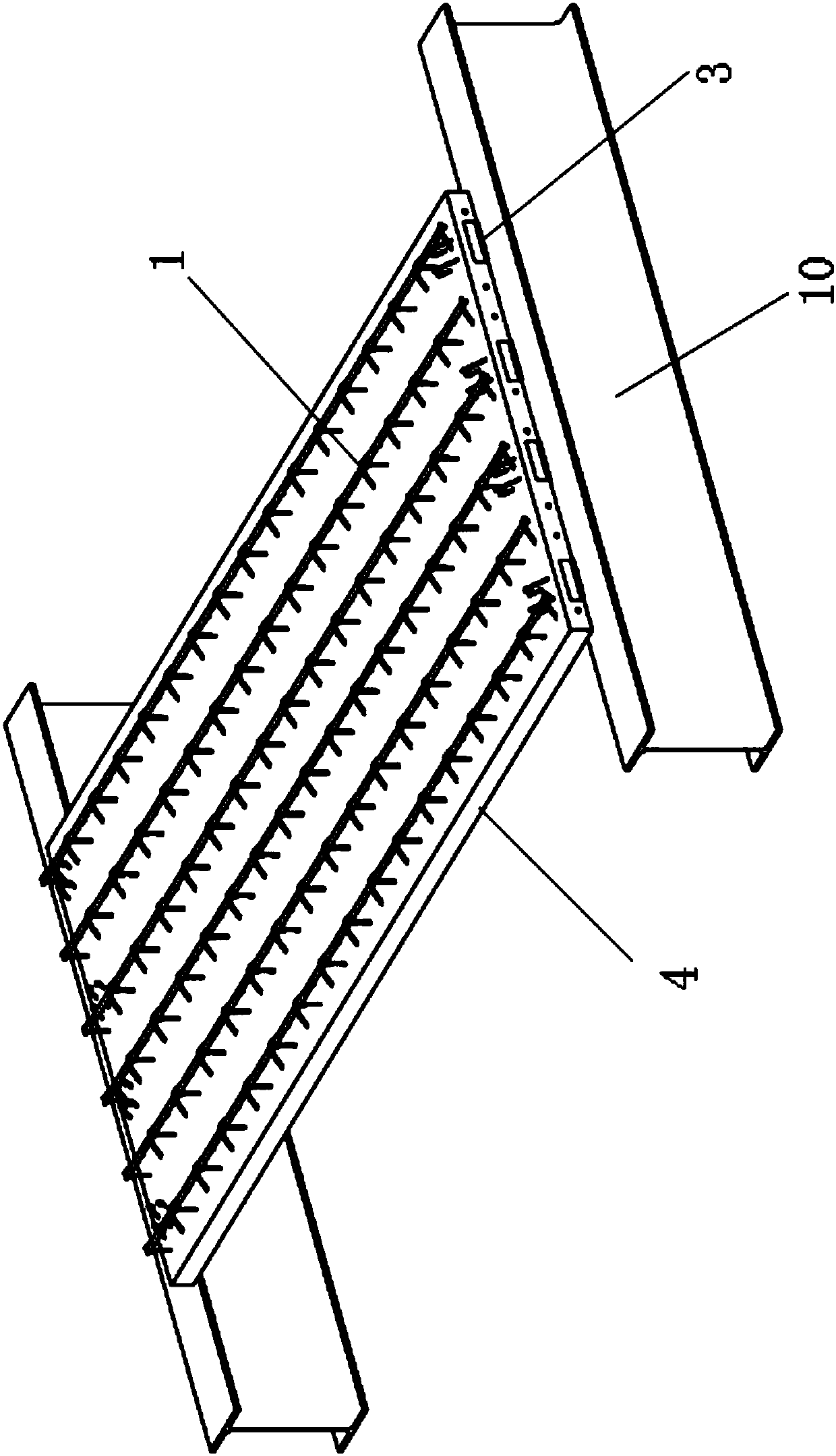
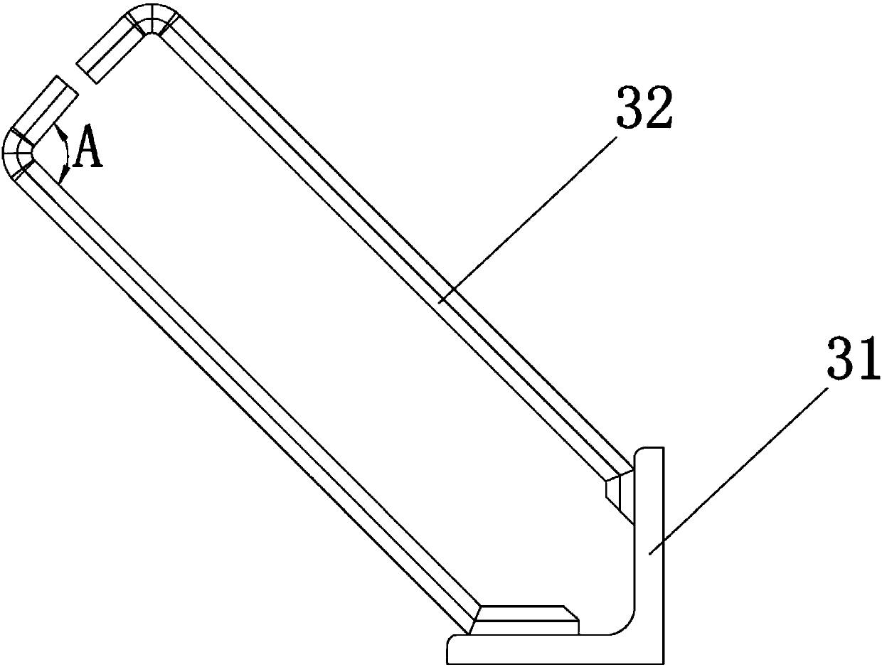
[0023] Please refer to the attached figure 1 to attach Figure 5 As shown, the present invention is a laminated floor slab for a prefabricated steel structure, which is arranged on a steel beam 10 (or other steel structure system), which consists of a steel truss 1, bottom bars 2, embedded parts 3 and prefabricated layers 4 It consists of several parts, wherein, the steel bar truss 1, the bottom bar 2, and the embedded parts 3 are pre-embedded in the prefabricated layer 4 respectively.

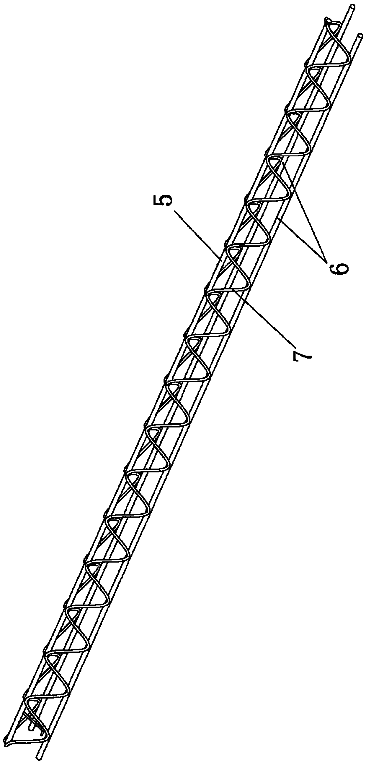
[0024] The steel bar truss 1 is processed and formed by the assembly line of the factory, and it is not only a part of the reinforcement in the laminated floor, but also plays a supporting role. The steel bar truss 1 is composed of upper chord steel bars 5 , lower chord steel bars 6 , web bar steel bars 7 and the like. The upper chord reinforcement bars 5 and the lower chord reinforcement bars 6 are arranged parallel to each other and arranged in an isosceles triangle. The web steel bars 1 ...


PUM


Abstract

The invention relates to a composite floor slab special for an assembled steel structure. The composite floor slab is arranged on a steel beam and comprises a rebar truss, bottom rebars, embedded members and a prefabricated layer, the rebar truss comprises upper-chord rebars, lower-chord rebars and web member rebars, the upper-chord rebars and the lower-chord rebars are arranged parallelly to eachother and are in isosceles triangle distribution, and the web member rebars are welded between the upper-chord rebars and the lower-chord rebars; the bottom rebars are bound together with the lower-chord rebars of the rebar truss and are perpendicular to the same, the rebar truss, the bottom rebars and the embedded members are embedded in the prefabricated layer, and the embedded members are connected with the steel beam. By the composite floor slab, the problem in connection between conventional composite floor slabs and steel structures is solved; through effective connection with a steel structure body, integrity and aseismicity of the structure are improved, so that the composite floor slab can play a great role in the field of the assembled steel structure.

Description

【Technical field】 [0001] The invention relates to a floor slab, in particular to a special laminated floor slab for an assembled steel structure, which belongs to the technical field of assembled buildings. 【Background technique】 [0002] Pushed by national policies, prefabricated steel structure buildings have become a development trend. At present, the domestic steel structure itself is relatively mature, but the three-plate system enclosure technology that matches the steel structure is relatively backward. [0003] As one of the three-slab system, the floor slabs of the existing steel structure buildings have the following methods: 1. On-site cast-in-place formwork, not only a large number of scaffolding supports, formwork operations, on-site steel bar binding operations and on-site concrete wet operations, but also need to wait for the next step. Only when the first floor is well maintained can the upper floor be poured, which is labor-intensive and affects the construc...

Claims


Application Information

Patent Timeline
Patent Type & Authority Applications(China)
IPC IPC(8): E04B5/17
CPCE04B5/17
Inventor 俞荣华秦光明赵力屠国平
Owner ZHEJIANG GREEN BUILDING INTEGRATION TECH CO LTD
Why Eureka
Try Eureka